
8(903)201-21-74
ООО "ЧетыреДатчика"
|
Оператор: 8(903)201-21-74 ООО "ЧетыреДатчика" |
|
Оператор: 8(903)201-21-74 ООО "ЧетыреДатчика" |
Главная страница Standalone-dvr users manual 1 2 3 4 5 ... 10
Note: Turn shuttle (outer ring) clockwise stands for right, counter clockwise stands for left. Turn jog (Inner dial) clockwise stands for down, counter clockwise stands for up. 2.2 Rear Panel 2.2.1 Overview Please refer to Figure 2-3 for real panel information. 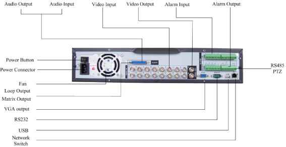 Figure 2-3 2.2.2 Connection Sample Here is a connection sample for your reference. See Figure 2-4. 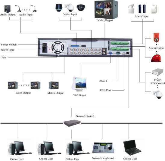 Note: 25-pin or 37-pin interface Model Audio Input Loop Output Matrix Output Bidirectional-Audio Input DH-DVR1604LB 16 channel NO NO 1 channel DH-DVR1604LBL 16 channel 4 channel 1 channel DH-DVR1604LBH 4 channel 16 channel 1 channel 1 channel 2.3 Remote Control The remote control interface is shown as in Figure 2-5. 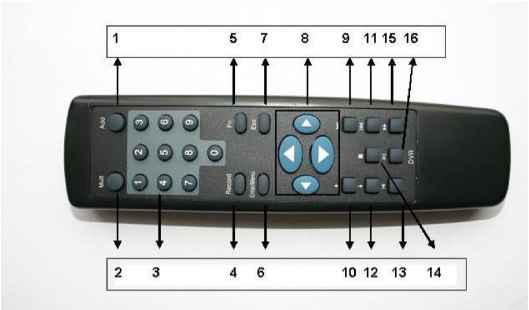 Figure 2-5
2.4 Mouse Control Left click mouse Have not login Real-time surveillance mode In menu selection mode In combo box Click number box or pass word box Pop up password input screen Enter the main menu Enter the select item Pop up pull down list Select number keyboard or character keyboard 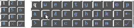 Double left click mouse  >: From small character to capitalized character <: From capitalized character to small character X: Delete al V: Confirm the current value Implement current selection Surveillance mode: and close current panel Such as double click one file name to playback the video In single mode: change to multiple-wind surveillance mode In multiple window mode: double click on video to change to full-screen display mo Right click mouse Press middle button Move mouse Drag mouse Surveillance mode In menu setting In number box In combo box In menu screen In list box Select current controls Select dynamic area In PTZ menu Pop up short cut menu Exit current menu without saving the settings Increase or decrease number Change selection Move cursor Move up and down Click one item to move menu 2.5 Virtual Keyboard & Front Panel 2.5.1 Virtual Keyboard The system supports two input methods: numeral input and English character (small and capitalized) input. Move the cursor to the text column, the text is shown as blue, input button pops up on the right. Click that button to switch between numeral input and English input (capitalized and small), Use > or < to shift between small character and capitalized character. 2.5.2 Front Panel Move the cursor to the text column. Click Fn key and use direction keys to select number you wanted. Please click enter button to input. 3 Installation and Connections Note: All the installation and operations here should conform to your local electric safety rules. 3.1 Check Unpacked DVR When you receive the DVR from the shipping agency, please check whether there is any visible damage to the DVR appearance. The protective materials used for the package of the DVR can protect most accidental clashes during transportation. Then you can open the box to check the accessories. Please check the items in accordance with the list on the warranty card. Finally you can remove the protective film of the DVR. 3.2 HDD Installation 3.2.1 Choose HDDs We recommend Seagate HDD of 7200rpm or higher. 3.2.2 Calculate HDD Size This series have no limit to HDD capacity. You can use 120G-750G HDD to guarantee higher stability. The formula of total HDD size is: Total Capacity (MB) = Camera Amount * Recording Hours * HDD Usage Per Hour (M/h) H.264 compression is ideal for standalone DVRs. It can save more than 30% HDD capacity than MPEG4. When you calculate the total HD capacity, you should estimate the average HDD capacity per hour for each channel. For example, for a 4-ch DVR, the average capacity of HDD usage per hour per channel is 200M/h. Now if you hope the DVR can record the video 12 hours each day for 30 days, the total capacity of HDDs needed is: 4 channels * 30 days * 12 hours * 200 M/h = 288G. So you need to install one 300G HDD or 2 160G HDDs. 3.2.3 HDD Installation Data ribbons, fastening screws and smart HDD shelf design are already provided in the accessories. Notes: please pay attention to HDD jumper: If you just need to install one HDD, you can set the HDD to MASTER. If you install two HDDs to one IDE port, you need to set the farther one as MASTER and the other as SLAVE. Please dont set HDD as CS Enable or Cap Limit. Please follow the instructions below to install hard disk. 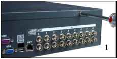 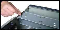 1. Remove the upper cover of the DVR 2. Remove the HDD bracket from internal unit 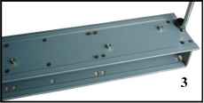 3. Dismantle the upper HDD bracket 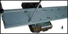 4. Install the HDD. Note the HDD is placed upside down. Please make sure bracket is in correct position. 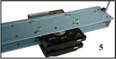 5. Screw the two bracket parts together 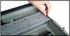
6. Set master/slave on the HDD 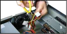 7. Fix the HDD bracket into the internal unit 8. Loosen the power cords for the HDD 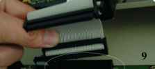 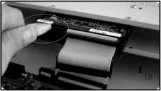 9. Connect the HDD with IDE port through data communication cable 10. Connect power cord to the HDD. 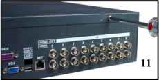 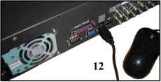 11. Place the upper cover back and screw firmly 12. Connect USB devices (USB mouse, USB portable hard drive, USB CD-RW) to the USB port directly After HDD installation, please check connection of data ribbon and power cord. Note: For LB SATA series, the HDD ports are SATA and there is no need to set master/slave HDD. 3.3 CD/DVD Burner Installation For built-in burner, you can dismantle front plate to install CD burner. This built-in burner should be set as MASTER. For USB burners, you need to install USB series burner. This series DVR is compatible with various burner brands popular in todays market. You can consult our local technical support or visit our website for more information. 3.4 Desktop and Rack Mounting 3.4.1 Desktop Mounting To prevent surface damage, please make sure that the rubber feet are securely installed on the four corners of the bottom of the unit. Position the unit to allow for cable and power cord clearance at the rear of the unit. Be sure that the air flow around the unit is not obstructed. 3.4.2 Rack Mounting The DVR occupies two rack units of vertical rack space. The hardware necessary to mount the DVR into a rack is supplied with the unit. Rear doors may be used only on rack columns that are more than 26 inches (66.0 cm) deep. Install the cabinet in ventilated place. Avoid extreme heat, humid or dusty conditions. You can use a soft dry brush to clean opening outlet, cooling fan and etc regularly. 3.5 Connecting Power Supply Please check input voltage and device power button match or not. We recommend you use UPS to guarantee steady operation, DVR life span, and other peripheral equipments operation such as cameras. 3.6 Connecting Video Input and Output Devices 3.6.1 Connecting Video Input The DVR automatically detects the video standard (PAL or NTSC) whenever you connect a video input. It accepts both color and black-and-white and analog video. NOTE: Enabling line lock on cameras may cause video distortion. There may be noise in the cameras power source. If video from one or more cameras is distorted, we recommend you disable line lock on the camera as your first troubleshooting step. If a video distribution amplifier is installed between the video source and the DVR, do not set the output video level above 1 Vp-p. To connect each video input: 1. Connect a coaxial cable to the camera or other analog video source. 2. Connect the coaxial cable to the video in connector on the rear panel. Please refer to Figure 3-1 for more information. NOTE: You need to use a BNC installation tool to connect coaxial cables to the rear panel.  Figure 3-1 3.6.2 Connecting Video Output This section provides information about physically connecting video display devices to the DVR. See Figure 3-2. If you connect the DVR with a TV monitor or VGA monitor, the DVR can automatically detects the monitor type. And without any output device, by default, the DVR is configured to use a TV monitor. In this case, if your application requires a VGA monitor, you have to press the button FN or Shift on the front panel. NOTE: Video output 1 and VGA cant display at the same time. But Video output 2 can display properly with Video Output 1 or VGA. 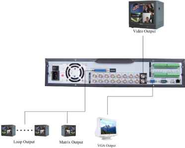 3.7 Connecting Audio Input & Output, Bidirectional Audio, Looping Video, Matrix For the 25-pin or 37-pin interface, different models include different functions. For example, DH-DVR1604LB has 16 audio inputs, 1 audio output, I bidirectional audio input. See Figure 3-3. 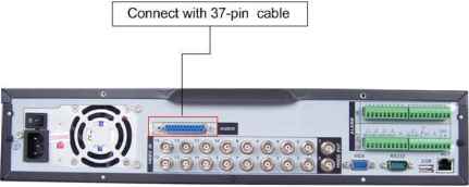 Figure 3-3 3.7.1 Audio Input/One Audio Output DH-DVR1604LBH has 16 looping video inputs, 4 matrix video outputs, 4 audio inputs, I bidirectional audio input, 1 audio output. Audio input, bidirectional audio input and audio output The DVR encodes audio and video signals simultaneously, which lets you control audio at the monitored location. To set up audio: 1. Make sure your audio input device matches the RCA input level. If the device and RCA input levels do not match, audio distortion problems may occur. 2. Make sure the audio connector is wired as follows: 3. Connect a line input device or pre-amplified microphone to the audio connector for the video channel on the rear panel. Please refer to Figure 3-4. 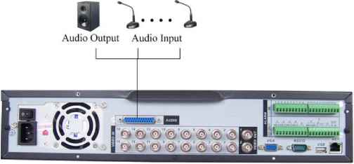 3.7.2 Looping video The DVR supports looping video. It passes the video input to a monitor or other analog video device. To use looping video: 1. Connect a coaxial cable to the video out connector on 37-pin interface Please note you need to use a BNC installation tool to connect coaxial cables to the rear panel. 2. Connect the other end of the coaxial cable to the analog device. 3.7.3 Matrix Video Output Use video matrix output connector during installation to display video sequentially from each video input. The unit displays each channel for selected seconds. You can use this feature to verify camera installation. To display video from each connected video source: 1. Connect a video monitor to the video matrix output connector. 2. Turn the DVR on, the monitor, and each video matrix output source. 3. Verify the video from each source and troubleshoot as necessary. Please refer to Figure 3-5. 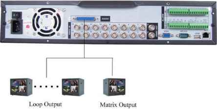 Matrix Output Figure 3-5 3.7.4 Alarm Input and Relay Output The DVR offers 16 alarm inputs for external signaling devices, such as door contacts or motion detectors. Each alarm input can be either normally open or normally closed. Once configured, an alarm input can invoke many different activities, including triggering a relay device, sending an alert to a security office or storing pre-alarm video to the DVR. 3.7.5 Alarm Input You should check your alarm input mode is grounding alarm input or not. For this series DVR, grounding signal is needed for alarm input. If you need to connect two units or one DVR and other device, please use relay to separate them. Please refer to Figure 3-6 for more information. 1 2 3 4 5 ... 10 |