
8(903)201-21-74
ООО "ЧетыреДатчика"
|
Оператор: 8(903)201-21-74 ООО "ЧетыреДатчика" |
|
Оператор: 8(903)201-21-74 ООО "ЧетыреДатчика" |
Главная страница Standalone-dvr users manual 1 2 3 4 5 6 7 ... 10
4.3.2.8 Backward playback and frame by frame playback
Remarks When system is in backward play or frame by frame playback mode, you can click play button to go to normal playback. Note: All the operations here (such as playback speed, channel, time and progress) have relationship with hardware version. Some series DVRs do not support some functions or playback speeds. 4.3.3 Calendar Click calendar iconlJ in Figure 4-10, system pops up calendar for your reference. Highlighted date means that there are record files in that day. You can click blue date to view file list. In Figure 4-11, there are video files in March 13th and 14th. Double click date to view file list. 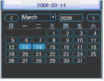 Figure 4-11 4.4 Record Setup (Schedule) When the system boots up, it is in default 24-hour regular mode. You can set record type and time in schedule interface. 4.4.1 Schedule Menu In the main menu, from setting to schedule, you can go to schedule menu. See Figure 4-12. There are three record types: R-Regular, MD-Motion detection, A- Alarm. In some series, system also supports C-Card) 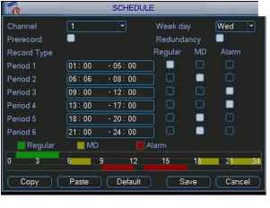 Figure 4-12 4.4.2 Basic Operation There are totally six periods. See Figure 4-12. Channel: Please select the channel number first. You can select all if you want to set for the whole channels. Week day: There are eight options: ranges from Saturday to Sunday and all. Redundancy: System supports redundancy backup function. You can highlight Redundancy button to activate this function. Please note, before enable this function, please set at least one HDD as redundant. Refer to the manual for detailed information. Prerecord: System supports prerecord function. The previous one to three seconds video before alarm occurs can be included in recorded video. Record types: There are three types: regular, motion detection (MD) and Alarm. Please highlight icon Я to select the corresponding function. After all the setups please click save button, system goes back to the previous menu. At the bottom of the menu, there is a color bar for your reference. Green stands for regular recording, yellow stands for motion detection and red stands for alarm recording. 4.4.1.1 Quick Setup This function allows you to copy one channel setup to another. After setting in channel 1, you can click paste button and turn to channel 2 and then click copy button. You can finish setting for one channel and then click save button or you can finish all setup and then click save button to memorize all the settings. 4.4.1.2 Redundancy Redundancy function allows you to memorize record file in several disks. These files are created, packaged and closed simultaneously. When there is file damage occurred in one disk, there is a spare one in the other disk. You can use this function to maintain data reliability and safety. In the main menu, from Setting to Schedule, you can highlight redundancy button to enable this function. See Figure 4-12. In the main menu, from Advanced to HDD management, you can set one or more disk(s) as redundant. You can select from the dropdown list. See Figure 4-13. System auto overwrites old files once hard disk is full. Please note only read/write disk or read-only disk can backup file and support file search function, so you need to set at least one read-write disk otherwise you can not record video. Note: About redundancy setup please note: If current channel is not recording, current setup gets activated when the channel begin recording the next time. If current channel is recording now, current setup will get activated right away, the current file will be packet and form a file, then system begins recording as you have just set. After all the setups please click save button, system goes back to the previous menu. lj HDD MANAGEMENT xl 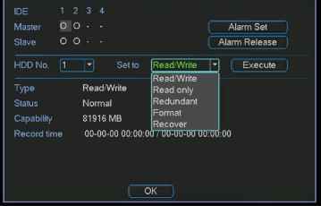 Figure 4-13 Playback or search in the redundant disk. There are two ways for you to playback or search in the redundant disk. Set redundant disk(s) as read-only disk or read-write disk (Main menu->Advanced->HDD management). See Figure 4-13.System needs to reboot to get setup activated. Now you can search or playback file in redundant disk. Dismantle the disk and play it in another PC. 4.5 Motion Detect 4.5.1 Go to Motion Detect Menu In the main menu, from Setting to Detect, you can see motion detect interface. See Figure 4-14. 4.5.2 Motion Detect Detection menu is shown as below. See Figure 4-14. Channel: select the channel you want to implement motion detection. Type: in the dropdown list, select motion detection item. Record channel: select the channel to activate recording function once alarm occurred. Please make sure you have set MD record in encode interface(Main Menu->Setting->Schedule) and schedule record in manual record interface(Main Menu->Advanced->Manual Record) Enable tour: Here is for you to activate tour between different cameras. Latch: when motion detection complete, system auto delays detecting for a specified time. The value ranges from 10-300(Unit: second) PTZ preset: Click set button, the interface is shown as in Figure 4-15.Here you can set preset for one or more channels. Region: click select button to set motion detection region. See Figure 4-16. Sensitivity: there are six levels. The six-level is of the highest sensitivity. Alarm output: when alarm occurred, system enables peripheral alarm devices. Show message: System pops up message in the screen to alert you once alarm occurred. Please highlight icon H to select the corresponding function. After all the setups please click save button, system goes back to the previous menu. Note: In motion detection mode, you can not use copy/paste to set channel setup since the video in each channel may not be the same. In Figure 4-15, you can left click mouse and then drag it to set a region for motion detection. Click Fn to switch between deployment and withdraw motion detection. After setting, click enter button to exit. 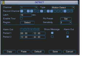 Figure 4-14 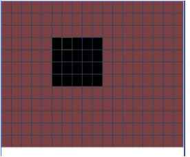 Figure 4-15 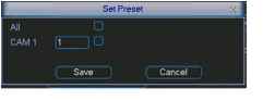 Figure 4-16 4.5.3 Video Loss In Figure 4-14, select video loss in the Type item. You can see the interface is shown as in Figure 4-17.This function allows you to be informed when video loss phenomenon occurred. You can enable alarm output channel and then enable show message function. Channel: select the channel you want to enable lens shading alarm. Type: please select video loss. Record channel: select the channel to record when video loss occurred. Alarm output: activate peripheral alarm device when video loss occurred. Enable tour: Here is for you to activate tour between different cameras. Latch: when motion detection completes, system auto delays detecting for a specified time. The value ranges from 10-300(Unit: second)
PTZ preset: Click set button to set preset for one or all channels. See Figure 4-16. Period 1/2: It is for you to set two periods (00.00-24.00). Alarm output: when video loss occurred, system enables peripheral alarm devices. Please highlight icon to enable this function Show message: System pops up message in the screen to alert you once alarm occurred. Please highlight icon to enable this function. 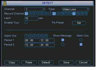 Figure 4-17 4.5.4 Camera Mask Detect When someone viciously masks lens, the system can alert you to guarantee video continuity. Camera mask detection interface is shown as in Figure 4-18. Channel: select the channel you want to enable camera mask detection function. Type: please select camera mask detect from the dropdown list. Record channel: select the channel to record when camera mask occurred. Alarm output: activate peripheral alarm device when camera mask occurred. Enable tour: Here is for you to activate tour between different cameras. Latch: when motion detection completes, system auto delays detecting for a specified time. The value ranges from 10-300(Unit: second) PTZ preset: Click set button to set preset for one or all channels. See Figure 4-16. Period 1/2: there are for you to set two periods (00.00-24.00). Alarm output: when camera masking occurred, system enables peripheral alarm devices. Please highlight icon to enable this function Show message: System pops up message in the screen to alert you once alarm occurred. Please highlight icon to enable this function Note: In this interface, copy/paste function is only valid for the same type, which means you can not copy a channel setup in video loss mode to camera mask detect mode. Record Channel Enable Tour Alarm Out Period 2 Type [Camera Mask Detecll liliil]® ® 03 oij ilij iiii iili (li (1? Pt: Preset ВИЗ® Show Message Alarm Out -08:00 I □ -20: 00 i □ Paste Default Figure 4-18 4.6 Alarm Setup and Alarm Activation Before operation, please make sure you have properly connected alarm devices such as buzzer. 4.6.1 Go to alarm setup interface In the main menu, from Setting to Alarm, you can see alarm setup interface. See Figure 4-19. 4.6.2 Alarm setup Alarm interface is shown as below. See Figure 4-19.
Alarm in: here is for you to set channel number. Source of alarm: there are two alarm sources: local input or network input. Type: normal open or normal close. Record channel: you can select proper channel to record alarm video (Multiple choices). At the same time you need to set alarm record in schedule interface (Main Menu->Setting->Schedule) and select schedule record in manual record interface (Main Menu->Advance->Manual Record). Latch: Here is for you to set proper delay duration. Value ranges from 10 to 300 seconds. System automatically delays specified seconds in turning off alarm and activated output after external alarm cancelled. PTZ preset: Here is for you to activate PTZ control. Relay out: select proper alarm activation output channel (multiple choices). Show message: System pops up message in the screen to alert you once alarm occurred. Period 1 and period 2: set proper time and alarm tips. Please highlight icon = to select the corresponding function. After all the setups please click save button, system goes back to the previous menu. 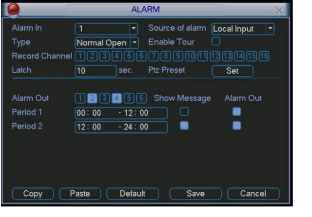 Figure 4-19 4.7 Backup Click backup icon in the main menu, there are two function items: detect device and backup files. 4.7.1 Detect Device Here is for you to view devices information. See Figure 4-20. DETECT DEVICE N Page Up Г Dete 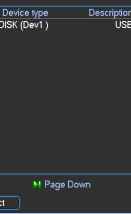 Total capabiliti 1 GL Figure 4-20 4.7.1 Backup Select backup device and then channel, file start time and end time. Click add button, system begins search. All matched files are listed below. System automatically calculates the capacity needed and remained. See Figure 4-21. system only backup files with a V before channel name. You can use Fn or cancel button to delete V after file serial number. Click backup button, you can backup selected files. There is a process bar for you reference. When the system completes backup, you can see a dialogue box prompting successful backup. 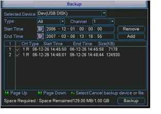 Figure 4-21 Click backup button, system begins burning. At the same time, the backup button becomes stop button. You can view the remaining time and process bar at the left bottom. See Figure 4-22. 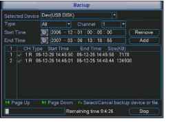 Figure 4-22 Tips: During backup process, you can click ESC to exit current interface; but the system will not terminate backup process. Note: When you click stop button during the burning process, there are two conditions for different devices: For CD/DVD burner device, the stop function becomes activated immediately and there is no data in the burner. For USB device, system can backup the data before you click stop button. For example, if there is a file of 10 minutes, when you click stop after five minutes backup, system only save the previous 5-minute data in the device. The file name format usually is: SN CH+channel number+time Y+M+D+H+M+S. In the file name, the YDM format is the same as you set in general interface. (Main Menu ->Setting ->General).You can visit our website to view listed CD-ROM type. 4.8 PTZ Control and Color Setup Note: All the operation here is based on DH-SD protocol. For PELCO protocols, there might be a little difference. 4.8.1 Cable Connection Please follow the procedures below to go on cable connection Connect the dome RS485 port to DVR 485 port.. Connect dome video output cable to DVR video input port. Connect power adapter to the dome. 4.8.2 PTZ Setup Note: The camera video should be in the current screen. Before setup, please check the following connections are right: PTZ and decoder connection is right. Decoder address setup is right. Decoder A (B) line connects with DVR A (B) line. Boot up the DVR, input user name and password. In the main menu, click setting, and then click Pan/Tilt Control button. The interface is shown as in Figure 4-23. Here you can set the following items: Channel: select the current camera channel. Protocol: select corresponding PTZ protocol(such as DH-SD1) Address: default address is 1. Baud rate: select corresponding baud rate. Default value is 9600. Data bits: select corresponding data bits. Default value is 8. Stop bits: select corresponding stop bits. Default value is 1. Parity: there are three options: odd/even/none. Default setup is none. 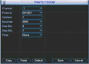 Figure 4-23 After all the setting please click save button. In one window display mode, right click mouse (click Fn Button in the front panel or click Fn key in the remote control). The interface is shown as in Figure 4-24. 1 2 3 4 5 6 7 ... 10 |