
8(903)201-21-74
ООО "ЧетыреДатчика"
|
Оператор: 8(903)201-21-74 ООО "ЧетыреДатчика" |
|
Оператор: 8(903)201-21-74 ООО "ЧетыреДатчика" |
Главная страница Standalone-dvr users manual 1 2 3 4 5 6 7 8 ... 10 View 1 View 4 View 9 View 16 WifnIitiiliWHiig Color Setting Search Record Alarm Output Alarm Input Main Menu Figure 4-24 Click Pan/Tilt/Zoom, the interface is shown as below. See Figure 4-25. Here you can set the following items: Step: value ranges fro 1 to 8. Zoom Focus iris Click icon Ы and У to adjust zoom, focus and iris. PAN/TILT/ZOOM e Zoom 9 e Focus О e Iris (Page Switch) Figure 4-25 In Figure 4-25, please click direction arrows (See Figure 4-26) to adjust PTZ position. There are totally 8 direction arrows.  Figure 4-26 4.8.3 3D Intelligent Positioning Key In the middle of the eight direction arrows, there is a 3D intelligent positioning key. See Figure 4-27. Click this key, system goes back to the single screen mode. Drag the mouse in the screen to adjust section size. It can realize PTZ automatically.  Here is a sheet for you reference.
4.9 Preset/ Patrol/Pattern/Scan In Figure 4-25, click the set button. The interface is shown as below. See Figure 4-28. Here you can set the following items: Preset Patrol(Tour) Pattern Border PANmLT/ZOOM xl Function Preset ГГ П1 Patrol! Patrol Pattern L Border (Tn Patrol No. [o I Set t Del Preset Figure 4-28 In Figure 4-25, click page switch button, the interface is shown as in Figure 4-29. Here you can activate the following functions: Preset Patrol(Tour) Pattern Aux on Aux off Auto scan Auto pan Light on 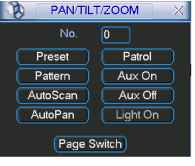 Note: The following setups are usually operated in the Figure 4-25,Figure 4-28 and Figure 4-29 . 4.9.1Preset Setup In Figure 4-25, use eight direction arrows to adjust camera to the proper position. In Figure 4-28, click preset button and input preset number. The interface is shown as in Figure 4-30. Now you can add this preset to one patrol (tour). 1 % PAN/TILT/ZOOM ~ x Function Preset === PatrolNo. [Q Patrol I-1 Pattern (I Set 1 Pattern Border Del Preset Figure 4-30 4.9.2 Activate Preset In Figure 4-29, please input preset number in the No. blank, and click preset button. 4.9.3 Patrol Setup (Tour setup) In Figure 4-28, click patrol button. The interface is shown as in Figure 4-31.Input preset number and add this preset to a patrol (tour). For each patrol (tour), you can input max 80 presets. PAN/TILT/ZOOM Function Preset l Pf .PatrolNo. [Г- Patrol I I- Pattern i Add Preset Border (( Del Preset Figure 4-31 4.9.4 Activate Patrol (tour) In Figure 4-28, input patrol (tour) number in the No. blank and click patrol button 4.9.5 Pattern Setup In Figure 4-28, click pattern button and then click begin button. The interface is shown as in Figure 4-32. Then you can go to Figure 4-25 to modify zoom, focus, and iris. Go back to Figure 4-32 and click end button. You can memorize all these operations as pattern 1. PANrriLT/ZOOM Function Pattern l P Patrol No. [ГП Patrol L-1 Pattern 1 I Begin Border (l End Figure 4-32 4.9.6 Activate Pattern Function In Figure 4-29, input mode value in the No. blank, and click pattern button. 4.9.7 Auto Scan Setup In Figure 4-28, click border button. The interface is shown as in Figure 4-23. Please go to Figure 4-25, use direction arrows to select camera left limit Then please go to Figure 4-33 and click left limit button Repeat the above procedures to set right limit. 1 pan/tilt/zo6m~ xl Function Pattern l Patrol No. [0 I Patrol - Pattern t Left 1 Figure 4-33 4.9.8 Activate Auto Scan In Figure 4-29, click Auto Scan button, the system begins auto scan. Correspondingly, the auto scan button changes to stop button. Click stop button to terminate scan operation. 4.10 Dome Menu Control In Figure 4-29, click page switch button, the interface is shown as below. See Figure 4-34. Click menu to enter dome menu. The direction arrows here are to control dome menu. Click page switch button, system goes back to Figure 4-25 PANrriLT/ZOOM Xlj 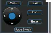 5 Understanding of Menu Operations and Controls 5.1 Menu Tree This series DVR menu tree is shown as below. 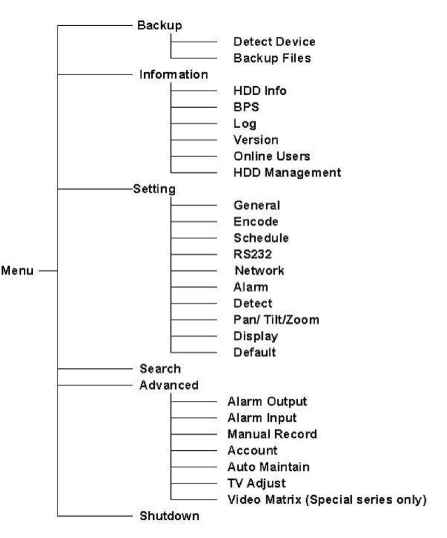 5.2 Main Menu When you login, the system main menu shows as below. See Figure 5-1 . There are totally six icons: search, Information, setting, backup, advanced and shutdown. Move the cursor to highlight the icon, then double click mouse to enter the sub-menu. 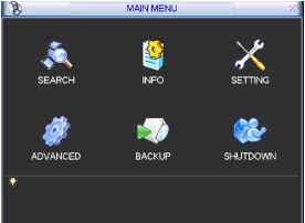 Figure 5-1 5.3 Setting In main menu, highlight setting icon and double click mouse. System setting interface is shown as below. See Figure 5-2. ЩЖ SETTING X I GENERAL ENCODE SCHEDULE RS232 NETWORK С i О ALARM DETECT PANn ILT/ZOOM DISPLAY DEFAULT Figure 5-2 5.3.1 General General setting includes the following items. See Figure 5-3. System time: here is for you to set system time Date format: there are three types: YYYYY-MM-DD: MM-DD-YYYYY or DD-MM- YYYY. Date separator: there are three denotations to separate date: dot, beeline and solidus. Time format: there are two types: 24-hour mode or 12-hour mode. Language: system supports various languages: Chinese (simplified), Chinese (Traditional), English, Italian, Japanese, French, Spanish (All languages listed here are optional. Slight difference maybe found in various series.) HDD full: Here is for you to select working mode when hard disk is full. There are two options: stop recording or rewrite. Pack duration: Here is for you to specify record duration. Default value is 60 minutes. DVR No: when you are using one remote control to control several DVRs, you can give a name to each DVR for your management. Video standard: There are two formats: NTSC and PAL. Auto logout: Here is for you to set auto logout interval once login user remains inactive for a specified time. Value ranges from 0 to 60 minutes. Note: since system time is very important, do not modify time casually unless there is a must. After all the setups please click save button, system goes back to the previous menu. System Time 2006 06 ( Date Separator ] Time Format 24-HOUR Language [ENGLISH Pacl< Duration 60 Video Standard PAL Auto Logout 10 Figure 5-3 5.3.2 Encode Encode setting includes the following items. See Figure 5-4. Channel: Select the channel you want. Compression: system supports H.264.Or you can select from the dropdown list. Resolution: System supports various resolutions, you can select from the dropdown list. For this model, we can support D1/CIF. Bit rate: system supports two types: CBR and VBR. Quality: There are six levels ranging from 1 to 6. Level six is the highest image quality. Frame rate: there are six levels: 1 f/s,2f/s,3f/s, 6f/s,12f/s,25f/s. (Some series DVRs only support PAL 25f/s ) Enable audio: you can turn on or off the audio. Cover area (Privacy mask): Here is for you to set window blanking section. You can drag you mouse to set proper section size. Time display: You can select system displays time or not. Channel display: You can select system displays channel number or not. System default setup is: Channel:1 Compression:H.264 Resolution: CIF/D1 Bit rate: CBR Quality: 4 Frame rate: 25f/s Please highlight icon S to select the corresponding function. Quality Frame Rate Overlay Cover-Area Time Display ENCODE Channel j Compression Н.264 Resolution CIF Bit Rate I GBR 25 FPS Channel Display Default :Save ) i Cancer Figure 5-4 5.3.3 Schedule Please refer to chapter 4.4 schedule. 5.3.4 RS232 RS232 interface is shown as below. Here are five items. See Figure 5-5. Function: There are various devices for you to select. Baud rate: You can select proper baud rate. Data bit: You can select proper data bit. Stop bit: There are three values: 1/1.5/2. Parity: there are three choices: none/odd/even. After all the setups please click save button, system goes back to the previous menu 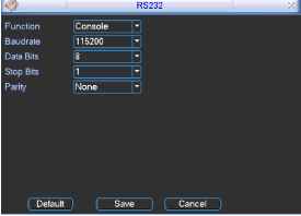 Figure 5-5 5.3.5 Network Here is for you to input network information. See Figure 5-6. IP address Subnet mask Gateway Service port: Default value is 37777. (System server port 37778 is reserved for network UDP use.) HTTP port: Default value is 80 Protocol: You can select proper protocol from the dropdown list. Max connection: support maximal 10 users. Properties: There are three options for you: FTP/NTP/Alarm center. You can select corresponding ways and then click properties button to go to setup interface. Authorization: Click authorization button please highlight icon = to enable IP authentication function. When you enable this function, only IP in the list can login this DVR. See Figure 5-7. After all the setups please click save button, system goes back to the previous menu. pi netvyork Щ< ip address subnet mask gateway service port protocol enable ddns. site name f 169 . 254 255 . 255 hostname ddnssen/erip q0 enable pppoe user name username default (authorization http port [s0 max connectionTo rproperties i [гп password Figure 5-6 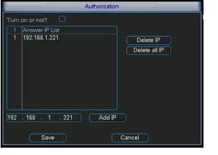 Figure 5-7 5.3.5.1 PPPoE Connection Enable PPPoE function and then input PPPoE name and PPPoE password you get from your ISP (Internet service provider). Click save button, you need to restart to activate your configuration. After rebooting, IP camera will connect to internet automatically. The IP in the PPPoE is the dynamic value. 5.3.5.2 Web visit via PPPoE There are two ways. a. visit via current IP After DVR connected with Internet by PPPoE, please get your devices current IP in Figure 5-6. Now you can visit this IP camera via this IP. b. Visit via DNS You need a PC of fixed IP in the internet and there is the DDNS software running in this PC. In other words, this PC is a DNS (domain name server). In network DDNS, input your PPPoE name you get from you IPS and server IP (PC with DDNS ) . Click save button and then reboot system. Click save button, system prompts for rebooting to get all setup activated. After rebooting, open IE and input as below: http: (DDNS server IP)/(virtual directory name)/webtest.htm e.g.: http: 10.6.2.85/DVR DDNS/webtest.htm.) Now you can open DDNSServer web search page. 5.3.5.3 FTP You need to download or buy FTP service tool (such as Ser-U FTP SERVER) to establish FTP service. Please install Ser-U FTP SERVER first. From start -> program -> Serv-U FTP Server -> Serv-U Administator. Now you can set user password and FTP folder. Please note you need to grant write right to FTP upload user. See Figure 5-8. 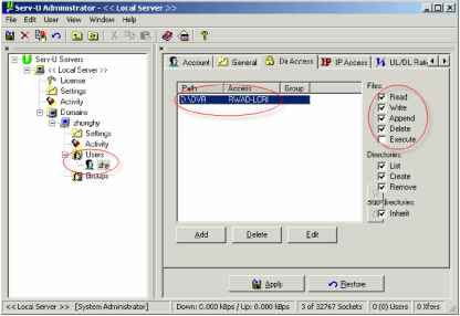 Figure 5-8 You can use a PC or FTP login tool to test setup is right or not. For example, you can login user ZHY to FTP: 10.10.7.7 and then test it can modify or delete folder or not. See Figure 5-9. 1 2 3 4 5 6 7 8 ... 10 |