
8(903)201-21-74
ООО "ЧетыреДатчика"
|
Оператор: 8(903)201-21-74 ООО "ЧетыреДатчика" |
|
Оператор: 8(903)201-21-74 ООО "ЧетыреДатчика" |
Главная страница Standalone-dvr users manual 1 ... 3 4 5 6 7 8 9 10 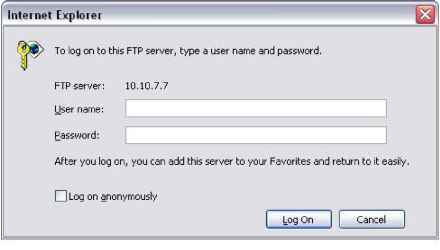 Figure 5-9 System also supports upload multiple DVRs to one FTP server. You can create multiple folders under this FTP. In Figure 5-6, select FTP and then click properties button. You can see the following interface. See Figure 5-10. I FTP SETTING xl enable host ip [Ъ dir name \2 user name \2 file length channel IT period 1 period 2 Q0: 00 00: 00 - 00: 00 - 00; 00 ?T 21 password 1 interval fO week fMon motion alarm □ □ □ no □ fOopy Default Cancel Figure 5-10 Please highlight the icon Я jn front of Enable to activate FTP function. Now FTP can upload alarm video and motion detection video. Please note, when you are using this function, please make sure current upload channel is in motion detection or alarm record status and there is video available. Here you can input FTP server address, port and etc. г . IP DIFttJAME pJF~ gSS4 MAMS ;гиг RLELENSm it. CHANNEL ff HTEWW. i 14 WEEK 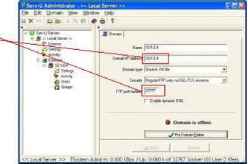 Figure 5-11 File length: upload file length. When setup is larger than the actual file length, system will upload the whole file. When setup here is smaller than the actual file length, system only uploads the set length and auto ignore the left section. Interval: in each channel, system only uploads the first video file in accordance with video type (alarm/motion detection) during the same period. For example, when interval value is 5 minutes, system only uploads the first motion detection or alarm file in each 5-minute. When interval value is 0, system uploads all corresponding files. Period 1 and period 2: you can set two periods for one each channel. System file name is shown as in Figure 5-12. 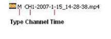 Figure 5-12 5.3.5.4 NTP You need to install SNTP server (Such as Absolute Time Server) in your PC first. In Windows XP OS, you can use command net start w32time to boot up NTP service. In Figure 5-6, select NTP and then click properties button. You can see the following interface. See Figure 5-13. Host IP: Input your PC address. Port: This series DVR supports TCP transmission only. Port default value is 123. Update interval: minimum value is 15(Unit: minute) Time zone: select your corresponding time zone here. Here is a sheet for your time zone setup.
Enable HostIP Port \й TimeZone 0 UpDatelnterval [o Cancel Figure 5-13 5.3.6 Alarm Please refer to chapter 4.6 Alarm Setup and Activation. 5.3.7 Detect Please refer to chapter 4.5 Detect. 5.3.8 Pan/Tilt/Zoom The pan/tilt/zoom setup includes the following items. Please select channel first. See Figure 5-14. Protocol: select corresponding PTZ protocol such as DH-SD1. Address: input corresponding PTZ address. Baud rate: select baud rate. Data bit: select data bit. Stop bit: select stop bit. Parity: there are three choices: none/odd/even. After all the setups please click save button, system goes back to the previous menu. For detailed setup, please refer to chapter 4.9 preset/patrol/pattern/scan. 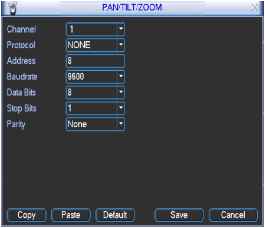 Figure 5-14 5.3.9 Display Display setup interface is shown as below. See Figure 5-15. Transparency: Here is for you to adjust transparency. The value ranges from 128 to 255. Channel name: Here is for you to modify channel name. Please note all your modification here only applies to DVR local end. You need to open web or client end to refresh channel name. Time display: You can select display time or not. Channel display: You can select channel name or not. Overlay information: System displays some information in the screen for your reference. Enable tour: activate tour function. Interval: Input proper interval value here. The value ranges from 5-200 seconds. In tour process, you can use mouse or click Shift to turn on window switch function. stands for opening switch function, stands for closing switch function. View1/4/9/16: System support 1/4/9/16 window tour. Please highlight icon Я to select the corresponding function. After all the setups please click save button, system goes back to the previous menu. fiS DISPLAY xl
Channel Name ( Modify Channel Display Ш 5.3.10 Default Click default icon, system pops up a dialogue box. You can highlight Я to restore default factory setup. See Figure 5-16. Select all General Encode Schedule RS232 Network Alarm Detect Pan/tilt/zoom Display Channel name Please highlight icon в to select the corresponding function. After all the setups please click save button, system goes back to the previous menu. Warning! System menu color, language, time display mode, video format, IP address, user account will not maintain previous setup after default operation! Please select setting entries tl~iat you want to restore default SCHEDULE NETWORK PAN/TILT/ZOOM Channel Name Figure 5-16 5.4 Search Please refer to chapter 4.3 Search. 5.5 Advanced Double click advanced icon in the main window, the interface is shown as below. See Figure 5-17. There are totally seven function keys: hard disk management, alarm output, alarm input, manual record, account, auto maintain, and TV adjust. 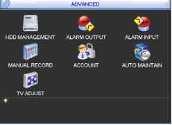 Figure 5-17 5.5.1 Hard Disk Management Here is for you to view and implement hard disk management. See Figure 5-18. You can set proper mode for each hard disk from the dropdown list. When you use redundant backup function, you can set one or more redundant HDD(s). Please note you need to set at least one read-write disk, otherwise system will not record video. For detailed information you can refer to chapter 4.4 Schedule. After all the setups please click save button, system needs to reboot to get all the modification activated. 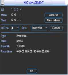 Figure 5-18 Click alarm set button, the interface is shown as below. See Figure 5-19. Please highlight icon в to select the corresponding function. You can enable one or more alarm setups. The lower limit ranges from 1% to 99%. Alarm channel number ranges from 1 to 6. Delay value is from 0 to 240 seconds. Please note when HDD capacity is not full system only alarms once! After all the setups please click OK button, system goes back to the previous menu Alarm Seti Alarm When no Disk or Errors Occgr Alarm When Free Space is Lower Lower Limit J99 ]% Alarm Output 13 Delay 30 sec. Show Message Ш Figure 5-19 5.5.2 Alarm Output Here is for you to set proper alarm output. Please highlight icon S to select the corresponding alarm output. After all the setups please click OK button, system goes back to the previous menu. See Figure 5-20. ALARM OUTPUT 1 2 3 4 5 6 □□□□□□ Figure 5-20 5.5.3 Alarm Input Here is for you to set alarm input. Please highlight icon S to select the corresponding input channel. After all the setups please click save button, system goes back to the previous menu. See Figure 5-21. ALARM INPUT 1 2 3 4 5 6 7 8 9 10 11 12 13 14 15 16   Figure 5-21 5.5.4 Manual Record Please refer to chapter 4.2.2 manual record. 5.5.5 Account Here is for you to implement account management. See Figure 5-22. Here you can: Add new user Modify user Add group Modify group Modify password. For account management please note: System account adopts two-level management: group and user. No limit to group or user amount. For group or user management, there are two levels: admin and user. The user name and group name can consist of eight bytes. One name can only be used once. There are four default users: admin/888888/666666 and hidden user default . Except user 6666, other users have administrator right. Hidden user default is for system interior use only and can not be deleted. When there is no login user, hidden user default automatically login. You can set some rights such as monitor for this user so that you can view some channel view without login. One user should belong to one group. User right can not exceed group right. About reusable function: this function allows multiple users use the same account to login. After all the setups please click save button, system goes back to the previous menu. Login Local Normal Normal Default User Modify User Modify Group Modify Password Figure 5-22 5.5.6 Auto Maintain Here you can set auto-reboot time and auto-delete old files setup. See Figure 5-23. You can select proper setup from dropdown list. After all the setups please click save button, system goes back to the previous menu. AUTO MAINTAJN Auto-Reboot System Every Monda> --at 00:00 Auto-Delete Old File; 30 Days ago Cancel TV ADJUST Top Deflate Bottom Deflate Left Deflate Right Deflate Brightness Figure 5-24 5.5.8 Video Matrix (For LBL Series and LBH Series) Some series DVR have the matrix and loop outputs. 5.5.8.1 Loop outputs They are just the same with video distributors. There are 16-ch video loop outputs from our DVR. The DVR video output can connect with other devices such as TV walls, analog matrix and so on. 5.5.8.2 Matrix outputs They are like the small-scale matrix. You can select any camera from our DVR to switch. And the output can also tour between the cameras. So the matrix outputs can be used to build TV walls and tour and display the cameras one by one. 5.5.8.3 Rear Panel Connection The rear panel is shown as below. See Figure 5-25. 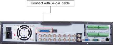 Figure 5-25 5.5.8.4 37-pin cable introduction There are three colors cable. See Figure 5-26. Black: for loop outputs, there are 16-ch loop outputs Blue: for matrix outputs, there are 4-ch matrix outputs White: for bi-direction talk, one is for audio in and the other is for audio out. 5.5.7 TV Adjust Here is for you to adjust TV output setup. See Figure 5-24. Please drag slide bar to adjust each item. After all the setups please click OK button, system goes back to the previous menu. 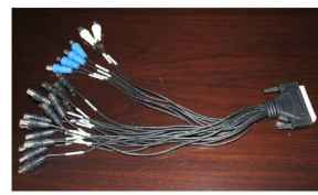 Figure 5-26 5.5.8.5 Matrix setup 5.5.8.5.1 Enter the Menu of Video Matrix In the menu, from Advanced to Video Matrix . See Figure 5-27. i# ADVANCEP XI HDD MANAGEMENT ALARM OUTPUT MANUAL RECORD ACCOUNT TV ADJUST VIDEO MATRIX ALARM INPUT AUTO MAINTAIN Figure 5-27 5.5.8.5.2 Right mouse menu In one-window display mode, right click mouse to select Video Matrix . See Figure 5-28. Panmit/Zoom Color Setting Alarm Output Alarm Input Vide0A1atrix Main Menu Figure 5-28 5.5.8.6 Video Matrix Interface and Application The video matrix interface is shown as in Figure 5-29. Now LBL series support 4-channel matrix outputs and LBH series support 1 channel 1 ... 3 4 5 6 7 8 9 10 |