
8(903)201-21-74
ООО "ЧетыреДатчика"
|
Оператор: 8(903)201-21-74 ООО "ЧетыреДатчика" |
|
Оператор: 8(903)201-21-74 ООО "ЧетыреДатчика" |
Главная страница Standalone-dvr users manual 1 ... 4 5 6 7 8 9 10 matrix output. All the operation below based on LBL series DVR. You can set for each channel. The function consists of two types. 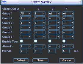 Figure 5-29 5.5.8.6.1 Single Tour Please enable tour function. Then set interval time and select corresponding cameras. You can select ALL to tour between all channels. Please note only Group 1 supports ALL function. Note: - - means that there is no alarm activation tour. If you have selected the ALL for the matrix output in Group 1, the matrix output will tour only between all cameras and the other groups setting will be null. 5.5.8.6.2 Alarm Tour Select the alarm in channel number from the dropdown list. If there is an alarm signal from the channel selected, the matrix output will go to tour as you set in the Alarm setting (Main Menu->Setting->Alarm). See Figure 5-30. Alarm tour has higher priority than single tour during this period, the single tour will stop. After alarm activation tour, the matrix output will continue single tour. H ALARM <J I 1 I ! Source of alarm [Local Input т NormalOpen \ Enable Tour □ Record Channel I sec. Ptz Preset 1ШВШ11]® Alarm Out ShowMessage Copy ) Paste 5.5.8.7 Examples 5.5.8.7.1 Example one In Figure 5-31, matrix outputs 1 , 3 , 4 tour between all cameras of the DVR. Matrix output 2 tours between CAM1, CAM6 and CAM7 of the DVR. The interval is five seconds. 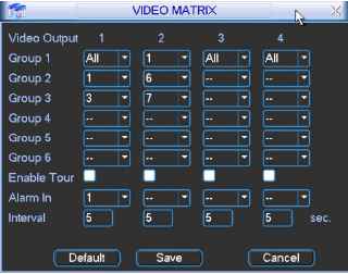 Figure 5-31 5.5.8.7.2 Example two In Figure 5-32, when alarm occurs in channel one, the activated matrix output one begins touring between CAM1, CAM3 and CAM4 of the DVR until alarm activation tour stops. Ш AURM xl Alarm In 1 [ Source of alarm [Local Input [- -I Type Normal Open - Enable Tour CL Record Channel Ц Щ Д [E Э (IIШ [E (Ш ID) 1Ш11П1 111 (III Delay 10 [sec. Ptz Preset Set ) Alarm Out Alarm Out Show Message Figure 5-32 5.6 Information Here is for you to view system information. There are totally five items: HDD (hard disk information), BPS (data stream statistics), Log and version, and online user. See Figure 5-33. 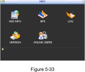 5.6.1 Hard Disk Information Here is to list hard disk type, total space, free space, video start time and status. See Figure 5-34. Note: Please remove the broken hard disk before you add a new one. Once there is a hard disk confliction, please check hard disk time and system time is the same or not. Please go to setting then general to modify system time. At last, reboot the system to solve this problem. In IDE information column, Omeans OK, X means error occurred > - means there is no disk. The serial number after the disk information such as O,which means it is current working disk. If disk is damaged, system shows as ? 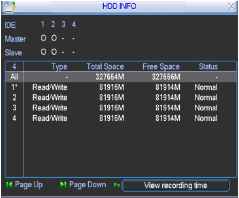 Figure 5-34 5.6.2 BPS Here is for you to view current video data stream (KB/s) and occupied hard disk storage (MB/h). See Figure 5-35. 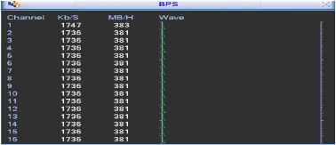 Figure 5-35 5.6.3 Log Here is for you to view system log file. System lists the following information. See Figure 5-36. 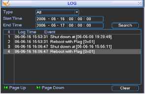 Figure 5-36 5.6.4 Version Here is for you to view some version information. See Figure 5-37. Channel Alarm in Alarm out System version: Baud rate: Start upgrade System Version 1.28 Build Date 2006-06-24 UPGRADE If you need to upgrade system now.please insert USB disk,ttien press ttie start button to start upgrade.Dont sfiut down thie power during upgrade! 5.6.5 Online Users Here is for you manage online users. See Figure 5-38. You can disconnect one user or block one user if you have proper system right. 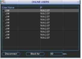 Figure 5-38 5.7 Exit Double click exit button, system pop up a dialogue box for you to select. See Figure 5-39. Logout menu user: log out menu. You need to input password when you login the next time. Restart application: reboot DVR. Shutdown: system shuts down and turns off power. Restart system: system begins rebooting. iLogoul menu user PassvlLogout menu user A зЦз^ iJReslatl applicalion Ш Shutdown [Reslar! system ADVAlL - - - DOWN t Logout the OSD menu or reset/restart the system. Afler idle lor standby time (no inputs), the system will exit OSD automatically Figure 5-39 6 About Auxiliary Menu 6.1 Go to Pan/Tilt/Zoom Menu In the one-window surveillance mode, right click mouse (click fn Button in the front panel or click AUX key in the remote control). The interface is shown as below: See Figure 6-1. View 1 i View 4 View 9 View 16 Pan.TillZoom Color Setting Search Record Alarm Output Alarm Input Main Menu Figure 6-1 Click Pan/Tilt/Zoom, the interface is shown as in Figure 6-2. Here you can set the following items: Zoom Focus iris Click icon у and у to adjust zoom, focus and iris. 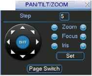 Figure 6-2 In Figure 6-2, please click direction arrows (See Figure 6-3 ) to adjust PTZ position. There are totally eight direction arrows. (Please note there are only four direction arrows in DVR front panel.)  6.1.1 3D Intelligent Positioning Key In the middle of the eight direction arrows, there is a 3D intelligent positioning key. See Figure 6-4 . Click this button, system goes back to the single screen mode. Drag the mouse in the screen to adjust section size.  Figure 6-4 Here is a sheet for you reference.
6.2 Preset /Patrol / Pattern /Border Function In Figure 6-2 click the set button. The interface is shown as below: Here you can set the following items:
Preset Patrol Pattern Border PAN/TILT/ZOOM Function Preset jl j f PatrolNo. [0~~ Patrol . =i Pattern I Set ) Border I Dei Preset Figure 6-5 In Figure 6-2, click page switch button, you can see an interface as in Figure 6-6. Here you can activate the following functions:
PAN/TILTZOOM 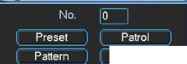 AuloScan AutoParT Aux On Aux Off Light Or [PageSwfltehj Figure 6-6 6.2.1 Preset Setup Note: The following setups are usually operated in the Figure 6-2, Figure 6-5 and Figure 6-6. In Figure 6-2, use eight direction arrows to adjust camera to the proper position. In Figure 6-5, click preset button and input preset number. The interface is shown as in Figure 6-7. Add this preset to one patrol number I PANrriLT/ZOOfi xl Function Preset Pf Patrol No. й~ Patrol 1 Pattern ( Set Border [ Del Pres Figure 6-7 6.2.2 Activate Preset In Figure 6-6 please input preset number in the No. blank, and click preset button. 6.2.3 Patrol Setup In Figure 6-5, click patrol button. The interface is shown as in Figure 6-8. Input preset number and then add this preset to one patrol. rig ~ PAN/tlLT/ZQOM~ X Function Preset Patrol I Pattern Border Patrol No. 0 (Add Pres rbel PreseT Figure 6-8 6.2.4 Activate Patrol In Figure 6-6, input patrol number in the No. blank and click patrol button 6.2.5 Pattern Setup In Figure 6-5, click pattern button and then click begin button. The interface shows like Figure 6-9. Please go to Figure 6-2 to modify zoom, focus, and iris. Go back to Figure 6-9 and click end button. You can memorize all these setups as pattern 1. I 1 PAM/TILTyZOOM  Function Pattern [Г PatrolNo. r Patrol L= Pattern I Begin Border I Fnri~ Figure 6-9 6.2.6 Activate Pattern Function In Figure 6-6 input mode value in the No. blank, and click pattern button. 6.2.7 Border Setup In Figure 6-5, click border button. The interface is shown as in Figure 6-10. Please go to Figure 6-2, use direction arrows to select camera left limit, and then please go to Figure 6-10 and click left limit button Repeat the above procedures to set right limit. 111 PAN/TILf/ZO0M~. ;< Function Pattern Pf PatrolNo. f Patrol \ Pattern 1 Left Border I fi Rinh Figure 6-10 6.2.8 Activate Border Function In Figure 6-6, click auto scan button, the system begins auto scan. Correspondingly, the auto scan button changes to stop button. Click stop button to terminate scan operation. 6.3 Dome Menu Control In Figure 6-6, click page switch button, the interface is shows as below. See Figure 6-11 Click menu to enter dome menu. The direction arrows here are to control dome menu. Click page switch button, system goes back to Figure 6-2. 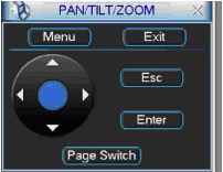 Figure 6-11 1 ... 4 5 6 7 8 9 10 |