
8(903)201-21-74
ООО "ЧетыреДатчика"
|
Оператор: 8(903)201-21-74 ООО "ЧетыреДатчика" |
|
Оператор: 8(903)201-21-74 ООО "ЧетыреДатчика" |
Главная страница Standalone-dvr users manual 1 ... 6 7 8 9 10 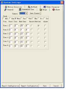 Figure 7-24 7.6.4 Image Click image button, the interface is shown as below. See Figure 7-25. Here you can select the image quality and protocols for each channel. Here you can set encode mode, quality and protocol for each channel. You can select from the dropdown list. FPS (PAL): there are several options: 1/2/3/6/12/25. (Some series DVR only support 25f/s PAL.) Data: there are two data modes: CBR/VBR. Quality: There are six levels. The different data flux occupies different bandwidth and the transmission image qualities are also different. Among them, level 6 needs the widest bandwidth and can reveal the best image quality. Please note you setup here only applies for image quality in web or client end. Resolution: there are several resolutions for you. You can select from the dropdown list. Alarm when video loss: You can enable or disable alarm function when alarm loss occurred. Network transmission protocol: Select protocol for network playback and monitor. You can select from the dropdown list. 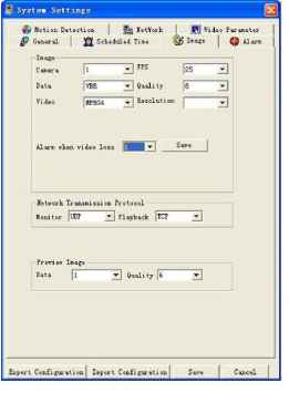 Figure 7-25 7.6.5 Alarm Here is for you to choose record channel and output port. See Figure 7-26. There are two alarm types: normal open or normal close. Delay time ranges from 10 to 300 seconds. You can draw a V before the check box to enable record camera and output port. 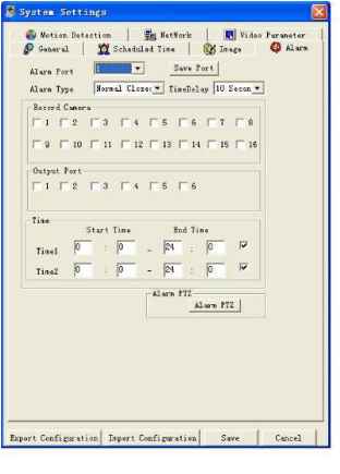
There are three options: preset, auto scan and tour. Figure 7-27 7.6.6 Motion Detection Motion detection will take effect exclude the time you set to schedule recording. See Figure 7-28. The blue area is the selected motion detection area. Click Full screen or right click mouse to view the motion detection area in full screen. After setting the area you can Save channel or Clear the area. Alarm output: Here you can enable alarm output channel. Please draw a V before the check box. Please note if you want to set this channel as motion detection recording, you need to turn off the schedule recording setup for this channel (Main Menu->Setting->Schedule). 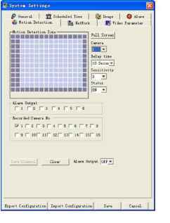 7.6.7 Network In Figure 7-26 click alarm PTZ button, you can see the following interface. See Figure 7-27. Network interface is shown as in Figure 7-29. 7.6.7.1 PPPoE Connection Set PPPOE as on, and then please input PPPoE name and PPPoE password you get from your ISP (Internet service provider). After saving it, you need to restart to active your configuration. After rebooting, IP camera will connect to internet automatically. The IP in the PPPoE IP is the dynamic value. 7.6.7.2 Web visit via PPPoE There are two ways. c. visit through current IP After IP camera connected with Internet by PPPoE, please get your devices current IP. Now you can visit this IP camera via this IP. d. Visit via DNS You need a PC of fixed IP in the internet and there is the DDNS software running in this PC. In other words, this PC is a DNS (domain name server). In network DDNS, input your PPPoE name you get from you IPS and server IP (PC with DDNS ) . Click save and then reboot system. Click save button, system prompts for rebooting to get all setup activated. After rebooting, open IE and input as below: http: (DDNS server IP)/(virtual directory name)/webtest.htm e.g.: http: 10.6.2.85/DVR DDNS/webtest.htm.) Now you can open DDNSServer web search page. 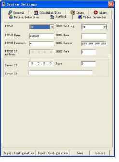 Figure 7-29 7.6.8 Video Parameter Video parameter setup interface is shown as in Figure 7-30. Before setup please select channel number first Audio enable: You can select to close or open audio. Auto white balance: You can select to close or open white balance. Image: You can adjust color, contrast, brightness, saturation and etc. After finishing all channels setup, you can click save at the button to save all configurations. 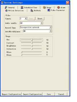 Figure 7-30 7.7 Assistant Click assistant setting, the interface is shown as below. See Figure 7-31. There are nine function keys. Please note Matrix control item only applies for some special series. 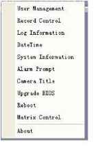 Figure 7-31 7.7.1 User Manage Here is for you to manage users and user groups. See Figure 7-32. You can click + to see the whole group list. 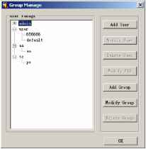 Figure 7-32 7.7.1.1 Add Group Click add group button to input group name. See Figure 7-33. 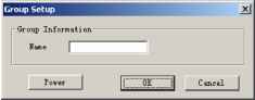 Figure 7-33 Click Power button to set group power. Click Save button to save configuration 7.7.1.2 Delete Group Click Delete Group button, the interface is shown as in Figure 7-34. Note: You can only delete empty group (E.g.: There is no user in current group). 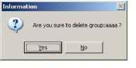 Figure 7-34 7.7.1.3 Modify Group Click modify group, the interface is shown as in Figure 7-35. You can modify group name and then click power button to set proper right for the whole group. 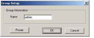 7.7.1.4 Add User Click Add User button the interface is shown as in Figure 7-36. Input user name, password, and then input password again to confirm. 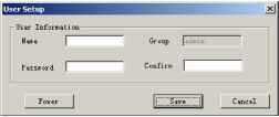 Figure 7-36 7.7.1.5 Power When you add new user or new group (such as in Figure 7-33,Figure 7-36. ), click power button, the interface is shown as in Figure 7-37. Here is for you to set users power. There are three power groups: main control power/monitor power/playback power. You can draw a V before the checkbox to enable corresponding function. 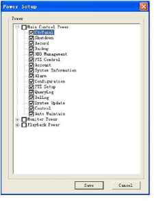 Figure 7-37 7.7.1.6 Modify user Select one user and then click modify user button, the interface is shown as in Figure 7-38. Here you can modify user name. 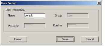 7.7.1.7 Delete user Select one user and then click delete user button, you can see the following dialogue box. See Figure 7-39. Click Yes to delete current user. 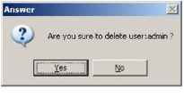 Figure 7-39 7.7.2 Record Control Click record control button the interface is shown as below. See Figure 7-40. You can select mode for each channel. 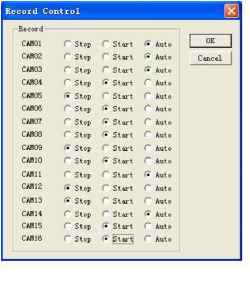 Figure 7-40 7.7.3 Log Information System can automatically backup all operation in log information. You can click this button to view detailed information. See Figure 7-41. Once you click save log button, the log files will be automatically saved in the root directory sucli as C:\ as a text file (e.g.: C:\ 10.1.27.193-log.txt) 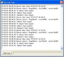 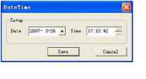 Figure 7-42 7.7.5 System Information Here you can view basic information of the system. See Figure 7-43. Here you can Turn on/off audio Select video type Select preview image Preview image Close or open auto tour monitoring View network data flux 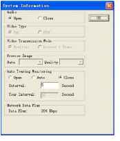 Figure 7-43 7.7.6 Alarm Prompt Here is for you to choose different alarm audios. See Figure 7-44. Here you can select system AlarmSound.wav file from folder system32 as your audio sound. 7.7.4 Date and Time Here you can modify system date and time. See Figure 7-42. 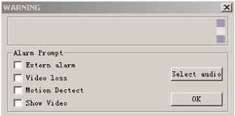 Figure 7-44 7.7.7 Channel Name Here is for you to modify channel name. The revised channel names will be displayed on the screen. The default setting of the channel name is Channel No.1 to Channel No.16. See Figure 7-45. Please note when you modify channel name in DVR end, this modification not applies to web end or standalone end, you need to use this interface to refresh. 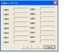 Figure 7-45 7.7.8 Upgrade BIOS Click upgrade BIOS button, the interface is shown as below. See Figure 7-46. Open the BIOS file (You can get from our local engineer or download from our web service) and then click send BIOS button. During the upgrade process, there is a process bar for your reference. npgrade BIOS, Сш-rent Frogress Cancel Figure 7-46 1 ... 6 7 8 9 10 |