
8(903)201-21-74
ООО "ЧетыреДатчика"
|
Оператор: 8(903)201-21-74 ООО "ЧетыреДатчика" |
|
Оператор: 8(903)201-21-74 ООО "ЧетыреДатчика" |
Главная страница Dvr features and function 1 ... 8 9 10 11 12 13 14 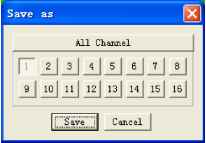 Figure 7-29 Network Network interface is shown as in Figure 7-30. This interface includes the following items: Max: Here you can set max connection amount. The value ranges from 0 to 10. 0 means no network connection is allowed. TCP port: default setup is 37777. Please note port 37778 is for network UDP port use only. HTTP port: default setup is 80. Transfer: here you can select the priority between fluency/video quality. Enable PPPoE In remote item, enable PPPoE function and then input PPPoE name and PPPoE password you get from your ISP (Internet service provider). See Figure 7-30. Click save button, you need to restart to activate your configuration. After rebooting, DVR will connect to internet automatically. The IP displayed in the IP address item is the dynamic value. You can use client-end software to visit current IP now. 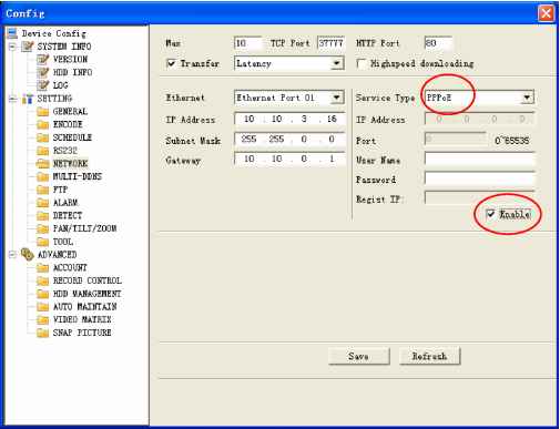 Enable DDNS You need a PC of fixed IP in the internet and there is the DDNS software running in this PC. In other words, this PC is a DNS (domain name server).see Figure 7-31. Please enable DDNS function and then input PC IP. Click save button and then reboot device. Now you can login via DDNS. Please open IE and then input http: (DDNS server IP)/ DDNServer / default.htm. for example, input http: 10.5.2.149/DDNServer/default.htm, you open a DDNS server web page. 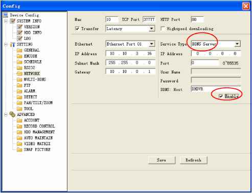 Figure 7-31 RS232 RS232 includes the following items. See Figure 7-32. Function: There are various devices for you to select. Console is for serial port or min-end platform to upgrade program. Keyboard is for you to use special keyboard to control current device. Baud rate: Please select as you desire. Data bit: The value ranges from 5 to 8. Stop bit: There are three options: 1/1.5/2. Parity: There are three options: none/odd /even. 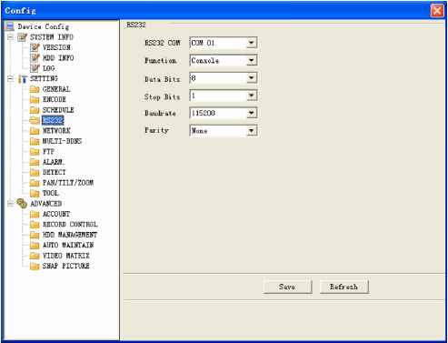 Figure 7-32 Mul-DDNS Here you can select DDNS type. This operation needs DVR device supported. See Figure 7-33. 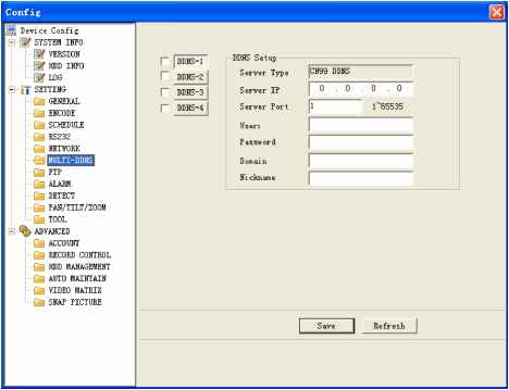 FTP Figure 7-33 After you completed setup here, system upload scheduled data to the specified FTP server regularly. Need device supported. In Figure 7-34, you need to input FTP server address, port, log in user name and password. Then you need to specify the destination directory to save files. File: here you can input uploaded file length (Unit: MB) if the file is smaller than the setup value here, system upload the whole file. If the file is larger than the setup value, system only uploads the setup value data and ignores the rest data. Interval: for one channel of the same record type if there is more than one alarm, system only uploads the first file. For example, if the interval is five minutes, then system only uploads the first alarm or motion detection file even though there are several alarms in these five minutes. If the setup is 0, then system upload all files. Time period: Click set button, you can an interface as in Figure 7-35. You can check the box to select the file type. System supports multiple choices. 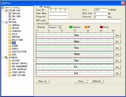 Figure 7-34 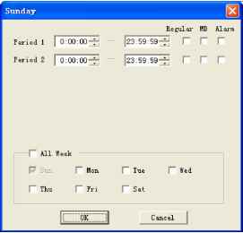 Figure 7-35 Alarm Please note before alarm setup, you need to properly connect alarm input and output device, send address and receive address. Click save button confirm current setup. Alarm setup includes the following items. See Figure 7-36. Event Type: you can select event type from the drop down list: Local alarm/Net alarm. Alarm in: Select corresponding alarm in channel Type: There are two options: normal open and normal close. Record channel: select record channel when alarm occurs. Please note you need to select alarm record in DVR schedule interface and enable schedule function in manual record interface. Alarm output: select alarm activation channel when alarm occurs. Please note channel 3 is to control +12V output. Show message: System can pop up a message to alarm you in the local host screen if you enabled this function. Email: System can send out email to alert you when alarm occurs. PTZ activation: Here you can set PTZ movement when alarm occurs. Such as go to preset x when there is an alarm. Click set button, the interface is shown as in Figure 7-37. Tour: Here you can enable tour function when alarm occurs. System supports multiple-window tour. Please go to chapter 5.3.9 Display for tour interval setup. 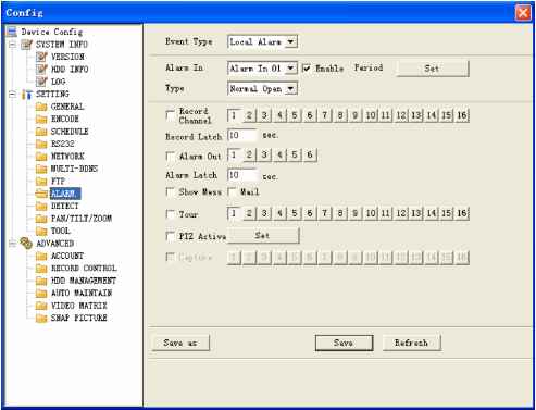 Figure 7-36 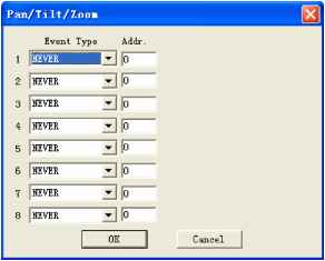 Figure 7-37 Detect Detect interface is shown as in Figure 7-38. Here includes the following items: Channel: Select channel name from the dropdown list. Type: There are three types: motion detection/Video loss/Camera mask detection. Record channel: Here you can select record channel (Multiple choices). Please make sure you have set MD record in encode interface(Main Menu->Setting->Schedule) and schedule record in manual record interface(Main Menu->Advanced->Manual Record) Period: Here is for you to set record period. Click set button, you can see an interface is shown as in Figure 7-39. In Figure 7-39, click time set button, you can see an interface is shown as in Figure 7-40. Here you can set time period. Sensitivity: There are six levels. The sixth level has the highest sensitivity. Region: If you select motion detection type, you can click this button to set motion detection zone. The interface is shown as in Figure 7-41. There are 192 zones (16*12). Right click mouse you can go to full-screen display mode. Do remember clicking OK button in Figure 7-41 to save your motion detection zone setup. Alarm output: Here you can select activated external peripheral device when alarm occurs. Show message. System can alert you on the local screen if you enabled this function. Mail: system can send out email to alert you when alarm occurs. Tour: Here you can enable tour function when alarm occurs in corresponding channel. System supports multiple-window tour. Please go to chapter 5.3.9 Display for tour interval setup. PTZ activation: Click set button, you can see an interface is shown as in Figure 7-42. System can go to corresponding preset when alarm occurs. 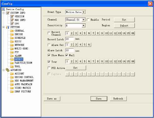 Figure 7-38 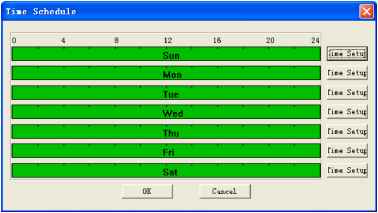 Figure 7-39 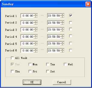 Figure 7-40 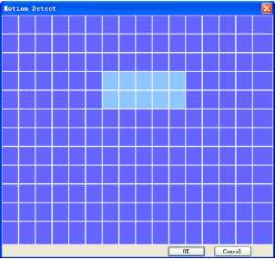 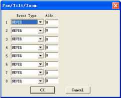 Figure 7-42 Pan/Tilt/Zoom Pan/Tilt/Zoom interface is shown as in Figure 7-43. Please note you have properly set dome address and all connections are right. Decoder: Select the dome connected channel. Protocol: select the corresponding dome protocol.(such as Pelco) Address: Set corresponding dome address. Default value is 1. Please note your setup here shall comply with your dome address; otherwise you can not control the speed dome. Baud rate: Select the dome baud rate. Default setup is 9600. Data bit: Default setup is 8. Stop bit: Default setup is 1. Parity: Default setup is none. 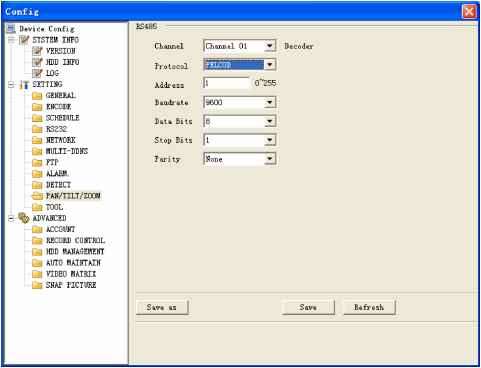 Figure 7-43 Tool Here you can export or import configuration information. See Figure 7-44. Save configuration data: Click export config button to save current setup as a file. Extension name is CFG. See Figure 7-45. Load configuration data: Click import config button, you can load a setup file. 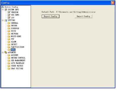 Figure 7-44 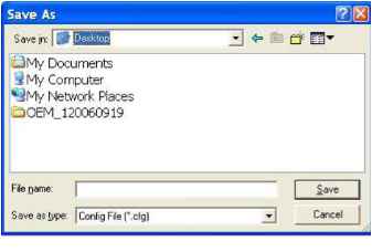 Figure 7-45 7.3.2.1 Advanced Advanced includes the following items. See Figure 7-46. Account HDD management Alarm input Alarm output Auto maintain Video matrix Snapshoot Account Account interface is shown as in Figure 7-46. Here you can add/delete user, add/delete group, modify user or group right, modify user password. 1 ... 8 9 10 11 12 13 14 |