
8(903)201-21-74
ООО "ЧетыреДатчика"
|
Оператор: 8(903)201-21-74 ООО "ЧетыреДатчика" |
|
Оператор: 8(903)201-21-74 ООО "ЧетыреДатчика" |
Главная страница Dvr features and function 1 2 3 4 5 6 ... 14 1. Connect a coaxial cable to the video out connector on 37-pin interface Please note you need to use a BNC installation tool to connect coaxial cables to the rear panel. 2. Connect the other end of the coaxial cable to the analog device. 3.7.3 Matrix Video Output Use video matrix output connector during installation to display video sequentially from each video input. The unit displays each channel for selected seconds. You can use this feature to verify camera installation. To display video from each connected video source: 1. Connect a video monitor to the video matrix output connector. 2. Turn the DVR on, the monitor, and each video matrix output source. 3. Verify the video from each source and troubleshoot as necessary. Please refer to Figure 3-5. 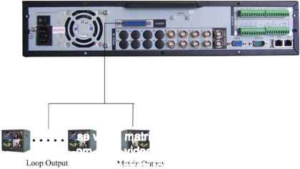 9 О Matrix Output Figure 3-5 3.7.4 Alarm Input and Relay Output This series DVR offers 4/8 alarm inputs for external signaling devices, such as door contacts or motion detectors. Each alarm input can be either normally open or normally closed. Once configured, an alarm input can invoke many different activities, including triggering a relay device, sending an alert to a security office or storing pre-alarm video to the DVR. 3.7.5 Alarm Input You should check your alarm input mode is grounding alarm input or not. For this series DVR, grounding signal is needed for alarm input. If you need to connect two units or one DVR and other device, please use a relay to separate them. Please refer to Figure 3-6 for more information. 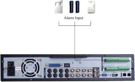 Figure 3-6 3.7.6 Alarm Output Do not connect alarm output port directly with high power load (no more than 1 A) in case of heavy current. You can use the co-contactor to realize the connection between the alarm output port and the load. Please refer to Figure 3-7 for more information. 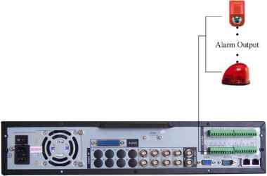 Figure 3-7 3.7.7 Alarm Input and Output Details You can refer to the following sheet and Figure 3-8 for alarm input and output information.
4/8-ch grounding alarm inputs. (Normal open or Normal close type) Please parallel connect COM end and GND end of the alarm detector (Provide external power to the alarm detector). Please parallel connect the Ground of the DVR and the ground of the alarm detector. Please connect the NC port of the alarm sensor to the DVR alarm input(ALARM) If you need to reset the touched-off alarm remotely, you can use DVR to supply controllable 12 V power to the alarm detector such as the smoke detector. Use the same ground with that of DVR if you use external power to the alarm device. 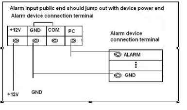 Figure 3-8 3.7.8 Relay Output Description 6-ways relay alarm output. Provide external power to external alarm device. To avoid over loading, please read the following relay parameters sheet carefully. (See below table) The controllable +12v can be used to restore the smoke detector. Please refer to Figure 3-9 for alarm input module information. 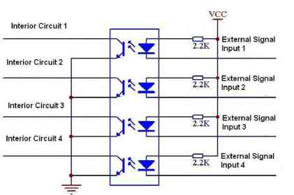 Figure 3-9 Please refer to Figure 3-10 for alarm output module information. 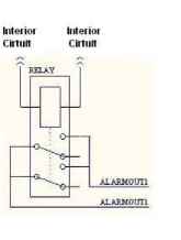 Figure 3-10 Relay Specification
3.8 RS232 You can connect the DVR with POS or Keyboard through RS232. With POS system, the DVR can communicate through RS232 and network. For the POS system, the DVR can integrate the text content and even search the record through the info. The series DVR also support NKB operation. You can operate the DVR from the keyboard controls instead of using the control pad on the front panel of the unit. To connect a NKB keyboard to the DVR: 1. Assemble the KBD keyboard according to the instructions in its accompanying installation manual. 2. Connect the KBD keyboard into one of the RS232 ports on the DVR or through network. 3.9 RS485 When the DVR receives a camera control command, it transmits that command up the coaxial cable to the PTZ device. RS485 is a single-direction protocol; the PTZ device cant return any data to the unit. To enable the operation, connect the PTZ device to the RS485(A,B) input on the DVR. Since RS485 is disabled by default for each camera, you must enable the PTZ settings first. This series DVRs support multiple protocols such as Pelco-D, Pelco-P. To connect PTZ devices to the DVR: 1. Connect RS485 A,B on the DVR rear panel. 2. Connect the other end of the cable to the proper pins in the connector on the camera. 3. Follow the instructions for configuring a camera to enable each PTZ device on the DVR. 3.10 Other Interfaces There are still other interfaces on the DVR, such as USB ports. You can refer to the Figure 3-11 for more information. 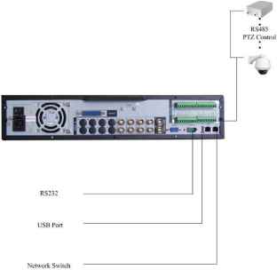 Figure 3-11 4 Overview of Navigation and Controls Before operation, please make sure you have properly installed HDDs and all the cable connections. 4.1 Login, Logout & Main Menu 4.1.1 Login When the system boots up, default video display is in multiple-window mode. Click Enter or left click mouse, you can see the login interface. See Figure 4-1. System consists of four accounts: Username: admin. Password: admin. (administrator, local and network) Username: 888888. Password: 888888. (administrator, local only) Username: 666666. Passwords: 666666(Lower authority user who can only monitor, playback, backup and etc.) Username: default. Password: default(hidden user) For your system security, please modify you password after first login. You can use USB mouse, front panel, remote controller or keyboard to input. About input method: Clickil23jto switch between numeral, English character (small/capitalized) and denotation. Note: Three times login failure in 30 minutes will result in system alarm and five times login failure will result in account lock! 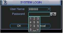 Figure 4-1 4.1.2 Main Menu After you logged in, the system main menu is shown as below. See Figure 4-2. There are total six icons: search, information, setting, backup, advanced and shutdown. You can move the cursor to highlight the icon, and then double click mouse to enter the sub-menu. 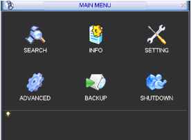 Figure 4-2 4.1.3 Logout There are two ways for you to log out. One is from menu option: In the main menu, click shutdown button, you can see an interface is shown as below. See Figure 4-3. 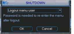 Figure 4-3 There are several options for you. See Figure 4-4. Logout menu user Restart application Shutdown Restart system Switcln user Figure 4-4 The other ways is to press power button on the front panel for at least 3 seconds, system will stop all operations. Then you can click the power button in the rear panel to turn off the DVR. 4.1.4 Auto Resume after Power Failure The system can automatically backup video and resume previous working status after power failure. 4.1.5 Replace Button Battery Please make sure to use the same battery model if possible. We recommend replace battery regularly (such as one-year) to guarantee system time accuracy. 4.2 Recording Operation 4.2.1 Live Viewing When you login, the system is in live viewing mode. You can see system date, time and channel name. If you want to change system date and time, you can refer to general settings (Main Menu->Setting->General). If you want to modify the channel name, please refer to the display settings (Main Menu->Setting->Display)
Note: Please refer to the following sheet for channel status. S stands for opening switch function, Ш stands for closing switch function. 4.2.2 Manual record Note: You need to have proper rights to implement the following operations. Please make sure the HDDs have been properly installed. 4.2.2.1 Manual record menu There are two ways for you to go to manual record menu. Right click mouse or in the main menu, Advanced->Manual Record. In live viewing mode, click record button in the front panel or record button in the remote control. Manual record menu is shown as in Figure 4-5. 4.2.2.2 Basic operation There are three statuses: schedule/manual/stop. Highlight icon o to select corresponding channel. Manual: the highest priority. After manual setup, all selected channels will begin ordinary recording. Schedule: channel records as you have set in recording setup (Main Menu- >Setting->Schedule) Stop: all channels stop recording. 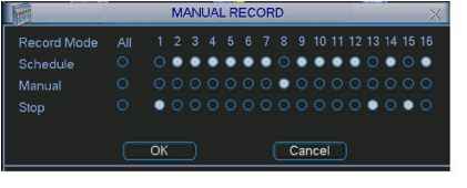 Figure 4-5 4.2.2.3 Enable/disable record Please check current channel status: o means it is not in recording status, means it is in recording status. You can use mouse or direction key to highlight channel number. See Figure 4-6. MANUAL RECORD Record Mode All 123456789 10 11 12 13 14 15 16 Schedule О © 0# 0*0# Manual О 0000000*0000000 0 SioD О ФОООООООООООФОФО Figure 4-6 4.2.2.4 Enable all channel recording Highlight о below All, you can enable all channel recording. All channel schedule record Please highlight ALL after Schedule . See Figure 4-7. When system is in schedule recording, all channels will record as you have previously set (Main menu->Setting->Schedule). The corresponding indication light in front panel will turn on. 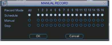 Figure 4-7 All channel manual record Please highlight ALL after Manual. See Figure 4-8. When system is in manual recording, all scheduled set up you have set in will be null ((Main menu->Setting->Schedule)). You can see indication light in front panel turns on, system begins manual record now. MANUAL RECORD Record Mode Schedule Л 2 3 4 5 6 7 9 10 11 12 13 14 15 16 oooooooooooooooo ooooooooooooooo Figure 4-8 4.2.2.5 Stop all channel recording Please highlight ALL after Stop . See Figure 4-9. System stops all channel recording no matter what mode you have set in the menu (Main menu->Setting->Schedule) 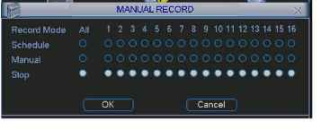 Figure 4-9 4.3 Search & Playback 4.3.1 Search Menu There are two ways for you to go to search menu. Click Pause/Play button in the remote control. Click search in the main menu. Search interface is shown as below. See Figure 4-10. Usually there are three file types: R: regular recording file. A: external alarm recording file. M: motion detection recording file C: card and pos test overlay recording file(For some special series only) System supports 1-ch playback. 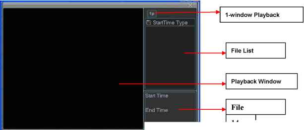 :.: 2007-06- 11 00:00:00 Size(KB) I   1 2 4 5 6 7 8 9 10 11 Figure 4-10 1 2 3 4 5 6 ... 14 |
|||||||||||||||||||||||||||||||||||||||||||||||||||||||||||||||||||||||||||||||