
8(903)201-21-74
ООО "ЧетыреДатчика"
|
Оператор: 8(903)201-21-74 ООО "ЧетыреДатчика" |
|
Оператор: 8(903)201-21-74 ООО "ЧетыреДатчика" |
Главная страница Dvr features and function 1 2 3 4 5 6 7 ... 14 Please refer to the following sheet for more information.
4.3.2 Basic Operation 4.3.2.1 Playback There are various search modes: video type, channel number or time. The system can max display 128 files in one screen. You can use page up/down button to view if there are more than one page. Select the file name and double click mouse (or click enter button), you can view file content. 4.3.2.2 Accurate playback Input time (h/m/s) in the time column and then click playback button, system can operate accurate playback. 4.3.2.3 Synchronized playback function when playback During playback process, click numeral key, system can switch to the corresponding channel video of the same time. 4.3.2.4 Digital zoom When the system is in full-screen playback mode, drag your mouse in the screen to select a section and then left click mouse to realize digital zoom. You can right click mouse to exit. 4.3.2.5 File backup System supports backup operation during search. You can draw a V before file name (multiple choices). Then click backup button (Button 14 in Figure 4-10). 4.3.2.6 Slow playback and fast playback Please refer to the following sheet for slow play and fast playback function.
4.3.2.7 Fast forward/fast backward and frame by frame playback
4.3.2.8 Backward playback and frame by frame playback Remarks When system is in backward play or frame by frame playback mode, you can click play button to go to normal playback.
Note: All the operations here (such as playback speed, channel, time and progress) have relationship with hardware version. Some series DVRs do not support some functions or playback speeds. 4.3.3 Calendar Click calendar iconli-l in Figure 4-10, system pops up calendar for your reference. Highlighted date means that there are record files in that day. You can click blue date to view file list. In Figure 4-11, there are video files in March 13th and 14th. Double click the date to view file list. 2007-06-26 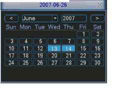 Figure 4-11 4.4 Record Setup (Schedule) When the system boots up, it is in default 24-hour regular mode. You can set record type and time in schedule interface. 4.4.1 Schedule Menu In the main menu, from setting to schedule, you can go to schedule menu. See Figure 4-12. There are three record types: R-Regular, MD-Motion detection. A-Alarm. SCHEDULE xl Channel [J [jJPreRecordU ]sec. RedundancyBSnapshot Week Day Wed - Record Type Regular MD Alarm Period 1 00 :00 Period 2 Q8 :0Q Period 3 10 :00 Period4 12 :00 Period 5 Period 6 20 :00 loo :00 -08 :00 -10 :00 -12 :00 -20 :00 -24 :00 -24 :00 (Regular 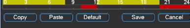 □ Alarm Figure 4-12 4.4.2 Basic Operation There are total six periods. See Figure 4-12. Channel: Please select the channel number first. You can select all if you want to set for the whole channels. Week day: There are eight options: ranges from Saturday to Sunday and all. Redundancy: System supports redundancy backup function. You can highlight Redundancy button to activate this function. Please note, before enable this function, please set at least one HDD as redundant.(Main menu->Advanced->HDD Management) Snapshoot: You can enable this function to snapshoot image when alarm occurs. Record types: There are three types: regular, motion detection (MD) and Alarm. Please highlight icon = to select the corresponding function. After all the setups please click save button, system goes back to the previous menu. At the bottom of the menu, there are color bars for your reference. Green stands for regular recording, yellow stands for motion detection and red stands for alarm recording. 4.4.1.1 Quick Setup This function allows you to copy one channel setup to another. After setting in channel 1, you can click paste button and turn to channel 2 and then click copy button. You can finish setting for one channel and then click save button or you can finish all setup and then click save button to memorize all the settings. 4.4.1.2 Redundancy Redundancy function allows you to memorize record file in several disks. These files are created, packaged and closed simultaneously. When there is file damage occurred in one disk, there is a spare one in the other disk. You can use this function to maintain data reliability and safety. In the main menu, from Setting to Schedule, you can highlight redundancy button to enable this function. See Figure 4-12. In the main menu, from Advanced to HDD management, you can set one or more disk(s) as redundant. You can select from the dropdown list. See Figure 4-13. System auto overwrites old files once hard disk is full. Please note only read/write disk or read-only disk can backup file and support file search function, so you need to set at least one read-write disk otherwise you can not record video. Note About redundancy setup: If current channel is not recording, current setup gets activated when the channel begin recording the next time. If current channel is recording now, current setup will get activated right away, the current file will be packet and form a file, then system begins recording as you have just set. After all the setups please click save button, system goes back to the previous menu. HDD MANAGEMENT 1 2 3 4 5 6 7 HDD No. ООО Read/Write Normal 79.99 GB Alarm Set ] Alarm Release Capacity 79.99 GB Record time 00-00-00 00:00:00 / 00-0 *) Setto I Read/Write -[Read/Write Read only Redundant Format .nn / nn nn Recover Execute Figure 4-13 Playback or search in the redundant disk. There are two ways for you to playback or search in the redundant disk. Set redundant disk(s) as read-only disk or read-write disk (Main menu->Advanced->HDD management). See Figure 4-13.System needs to reboot to get setup activated. Now you can search or playback file in redundant disk. Dismantle the disk and play it in another PC. 4.5 Detect 4.5.1 Go to Detect Menu In the main menu, from Setting to Detect, you can see motion detect interface. See Figure 4-14. There are three detection types: motion detection, video loss, camera masking. 4.5.2 Motion Detect Detection menu is shown as below. See Figure 4-14. Channel: select the channel you want to implement motion detection. Event type: from the dropdown list you can select motion detection type. Channel: select the channel to activate recording function once alarm occurred. Please make sure you have set MD record in encode interface(Main Menu->Setting->Schedule) and schedule record in manual record interface(Main Menu->Advanced->Manual Record) Latch: when motion detection complete, system auto delays detecting for a specified time. The value ranges from 10-300(Unit: second) Region: Click select button, the interface is shown as in Figure 4-15.Here you can set motion detection zone. There are 396(PAL)/330(NTSC) small zones. Sensitivity: System supports 6 levels. The sixth level has the highest sensitivity. Show message: System can pop up a message to alarm you in the local host screen if you enabled this function. Send email: System can send out email to alert you when alarm occurs.
PTZ activation: Here you can set PTZ movement when alarm occurs. Such as go to preset, tour &pattern when there is an alarm. Click select button, you can see an interface is shown as in Figure 4-16. Period: Click set button, you can see an interface is shown as in Figure 4-17. Here you can set for business day and non-business day. In Figure 4-17, click set button, you can see an interface is shown as in Figure 4-18. Here you can set your own setup for business day and non-business day. Anti-dither: Here you can set anti-dither time. Sensitivity: there are six levels. The sixth level has the highest sensitivity. Alarm output: when alarm occurred, system enables peripheral alarm devices. Tour: Here you can enable tour function when alarm occurs. It is a one-window tour. Please go to chapter 5.3.9 Display for tour interval setup. Snapshot: System can snapshoot when alarm occurs. Please highlight icon = to select the corresponding function. After all the setups please click save button, system goes back to the previous menu. Note: In motion detection mode, you can not use copy/paste to set channel setup since the video in each channel may not be the same. In Figure 4-15, you can left click mouse and then drag it to set a region for motion detection. Click Fn to switch between arm/withdraw motion detection. After setting, click enter button to exit. DETECT Event Type Enable Region Motion Detect 11 Channel Period Alarm Out Show Message Record Channel PTZ Activation Tour QSnapshot Select ] Sensitivity 3 ~ Set Anti-dither o sec. (2](D[D(5](6] Latch 10 sec. Send Email (inij [ю (1) И 0 0300 01 Select ] Delay 10 sec. (D(D[4)(D(D(D(D(D0OG3II1IBII1G1 I (D(l][D(5](6](T](8](D2gQ23(T3 03(1301 Default Cancel 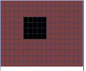 Figure 4-15 PTZ Activation CAM 1 [None CAMS [None CAM 5 iNone CAM 9 None CAM 11 (iw CAM 13 [None CAM 15 None  J [0 1 CAM 2 3 [0 I CAM 4 [0 I CAM 6 [0 I CAMS -) [0 I CAM 10 [0 I CAM 12 [0 I CAM 14 fO I CAM 16 Cancel Figure 4-16 [Work Day □ 00 :00 □ loo :00 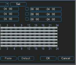 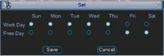 Figure 4-18 4.5.3 Video Loss In Figure 4-14, select video loss from the type list. You can see the interface is shown as in Figure 4-19.This function allows you to be informed when video loss phenomenon occurred. You can enable alarm output channel and then enable show message function. Channel: select the channel you want to enable lens shading alarm. Event type: please select video loss. Channel: select the channel to record when video loss occurred. Alarm output: activate peripheral alarm device when video loss occurred. Latch: when motion detection complete, system auto delays detecting for a specified time. The value ranges from 10-300(Unit: second) Show message: System can pop up a message to alarm you in the local host screen if you enabled this function. Send email: System can send out email to alert you when alarm occurs. PTZ activation: Here you can set PTZ movement when alarm occurs. Such as go to preset, tour & pattern when there is an alarm. Click select button, you can see an interface is shown as in Figure 4-16. Period: Click set button, you can see an interface is shown as in Figure 4-17. Here you can set for business day and non-business day. In Figure 4-17, click set button, you can see an interface is shown as in Figure 4-18. Here you can set your own setup for business day and non-business day. Sensitivity: there are six levels. The sixth level has the highest sensitivity. Alarm output: when alarm occurred, system enables peripheral alarm devices. Tour; Here you can enable tour function when alarm occurs. It is a one-window tour. Please go to chapter 5.3.9 Display for tour interval setup. Snapshot: System can snapshoot when alarm occurs. Video Loss R CInannel Enable Period Alarm Out Show Message BRecord Channel QPTZ Activation □Tour QSnapshot (D(D(4)(5](i] Latch 10 sec. QSend Email Select ) Delay 10 sec. I (D(D(D(5](i](D(D (9)000113010301 I (D (D (D (5) (D (7) (D (9)0003010103 01 Figure 4-19 4.5.4 Camera Masking When someone viciously masks lens, the system can alert you to guarantee video continuity. Camera masking interface is shown as in Figure 4-20. Channel: select the channel you want to enable camera mask detection function. Event type: please select camera mask detect from the dropdown list. Channel: select the channel to record when camera mask occurred. Alarm output: activate peripheral alarm device when camera mask occurred. Enable tour: Here is for you to activate tour between different cameras. Latch: when motion detection complete, system auto delays detecting for a specified time. The value ranges from 10-300(Unit: second) Show message: System can pop up a message to alarm you in the local host screen if you enabled this function. Send email: System can send out email to alert you when alarm occurs. PTZ activation: Here you can set PTZ movement when alarm occurs. Such as go to preset, tour &pattern when there is an alarm. Click select button, you can see an interface is shown as in Figure 4-16. Period: Click set button, you can see an interface is shown as in Figure 4-17. Here you can set for business day and non-business day. In Figure 4-17, click set button, you can see an interface is shown as in Figure 4-18. Here you can set your own setup for business day and non-business day. Sensitivity: there are six levels. The six-level has the highest sensitivity. Alarm output: when alarm occurred, system enables peripheral alarm devices. Tour: Here you can enable tour function when alarm occurs. It is a one-window tour: Please go to chapter 5.3.9 Display for tour interval setup. Snapshoot: System can snapshoot when alarm occurs. Note: In this interface, copy/paste function is only valid for the same type, which means you can not copy a channel setup in video loss mode to camera masking mode. Enable Period Camera MasklR Channel Alarm Out Show Message Record Channel О PTZ Activation □Tour QSnapshot (D(D(4](5](D Latch 10 sec. QSend Email (2](i](4](D(i](T](D(i]sgoG3S30GlS§ (Т|(Т|И[Г|(6](Т)[8](1]ИО0003Е35§ 1(2](1](4](5](б](7](8](9]иоез00зед5§ Cancel Figure 4-20 4.6 Alarm Setup and Alarm Activation Before operation, please make sure you have properly connected alarm devices such as buzzer. 4.6.1 Go to alarm setup interface In the main menu, from Setting to Alarm, you can see alarm setup interface. See Figure 4-21. 4.6.2 Alarm setup Alarm interface is shown as below. See Figure 4-21.
Alarm in: here is for you to select channel number. Event type: there are two types. One is local input and the other is network input. Type: normal open or normal close. PTZ activation: Here you can set PTZ movement when alarm occurs. Such as go to preset, tour& pattern when there is an alarm. Click select button, you can see an interface is shown as in Figure 4-25. Period: Click set button, you can see an interface is shown as in Figure 4-23. Here you can set for business day and non-business day. In Figure 4-26, click set button, you can see an interface is shown as in Figure 4-27. Here you can set your own setup for business day and non-business day. Anti-dither: Here you can set anti-dither time. Show message: System can pop up a message to alarm you in the local host screen if you enabled this function. Send email: System can send out email to alert you when alarm occurs. Record channel: you can select proper channel to record alarm video (Multiple choices). At the same time you need to set alarm record in schedule interface (Main Menu->Setting->Schedule) and select schedule record in manual record interface (Main Menu->Advance->Manual Record). 1 2 3 4 5 6 7 ... 14 |