
8(903)201-21-74
ООО "ЧетыреДатчика"
|
Оператор: 8(903)201-21-74 ООО "ЧетыреДатчика" |
|
Оператор: 8(903)201-21-74 ООО "ЧетыреДатчика" |
Главная страница Dvr features and function 1 2 3 4 5 6 7 8 ... 14 Latch: Here is for you to set proper delay duration. Value ranges from 10 to 300 seconds. System automatically delays specified seconds in turning off alarm and activated output after external alarm cancelled. Tour: Here you can enable tour function when alarm occurs. It is a one-window tour: Please go to chapter 5.3.9 Display for tour interval setup. Snapshot: System can snapshoot when alarm occurs. Please highlight icon в to select the corresponding function. After all the setups please click save button, system goes back to the previous menu. IД ! ALARM x 1 Event Type Enable Period Alarm Out Show Message Record Channel PTZ Activation [Snapshot [Local Alarm p] Alarm In Type Normal Open Set ] Anti-dither 0 sec. KDdJSSd) Latch 10 [see. BSend Email Select ] Delay 10 [see. [2][3](4](5](6](7)(8)[9]0O000030B Figure 4-21 PTZ Activation CAM 1 [None CAMS [None CAM 5 [None CAM 7 [None CAM 9 [None CAM 11 [iw CAM IS [None CAM 15 iNone CAM 2 CAM 4 CAM 6 (0 I CAM 8 3 fO I CAM 10 3 fO I CAM 12 3 (0 1 CAM 14 71 0 I CAM 16 Cr Cancel 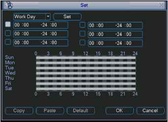 Figure 4-23 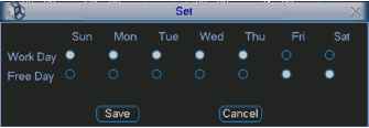 Figure 4-24 4.7 Backup DVR support various backup devices such as CD-RW,DVD driver, USB backup and network download. Here we introduce USB backup first. You can refer to Chapter 7 Web Client Operation for network download backup operation. 4.7.1 Detect Device Click backup button, you can see an interface is shown as in Figure 4-25. Here is for you to view devices information. 4 NamatTyps) 1 V Dev(USB DISK) 2 Dev(IDE DVD/CD-RW) 3 Dev(1394 DHFS) 4- y Dev(USB DVD/CD-RW) pace/Total capacity Device Statu I.OOGB/IOOGB Ready IQOGB/I.OOGB Ready 1.00GB/1.00GB Ready I.OOGB/I.OOGB Ready Page Up Page Down Select/Cancel backup device or file. Detect j i Backup ) [ Erase j { Stop j 4.7.1 Backup Select backup device and then channel, file start time and end time. Click add button, system begins search. All matched files are listed below. System automatically calculates the capacity needed and remained. See Figure 4-26. system only backup files with a v before channel name. You can use Fn or cancel button to delete V after file serial number. Click backup button, you can backup selected files. There is a process bar for you reference. When the system completes backup, you can see a dialogue box prompting successful backup. 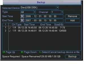 Figure 4-26 Click backup button, system begins burning. At the same time, the backup button becomes stop button. You can view the remaining time and process bar at the left bottom. See Figure 4-27. 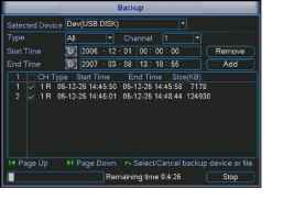 Figure 4-27 Tips: During backup process, you can click ESC to exit current interface; but the system will not terminate backup process. Note: When you click stop button during the burning process, there are two conditions for different devices: For CD/DVD burner device, the stop function becomes activated immediately and there is no data in the burner. For USB device, system can backup the data before you click stop button. For example, if there is a file of 10 minutes, when you click stop after five minutes backup, system only save the previous 5-minute data in the device. The file name format usually is: SN CH+channel number+time Y+M+D+H+M+S. In the file name, the YDM format is the same as you set in general interface. (Main Menu ->Setting ->General).You can visit our website to view listed CD-ROM type. 4.8 PTZ Control and Color Setup Note: All the operations here are based on PELCOD protocol. For other protocols, there might be a little difference. 4.8.1 Cable Connection Please follow the procedures below to go on cable connection Connect the dome RS485 port to DVR 485 port. Connect dome video output cable to DVR video input port. Connect power adapter to the dome. 4.8.2 PTZ Setup Note: The camera video should be in the current screen. Before setup, please check the following connections are right: PTZ and decoder connection is right. Decoder address setup is right. Decoder A (B) line connects with DVR A (B) line. Boot up the DVR, input user name and password. In the main menu, click setting, and then click Pan/Tilt Control button. The interface is shown as in Figure 4-28. Here you can set the following items: Channel: select the current camera channel. Protocol: select corresponding PTZ protocol(such as PELCOD) Address: default address is 1. Baud rate: select corresponding baud rate. Default value is 9600. Data bits: select corresponding data bits. Default value is 8. Stop bits: select corresponding stop bits. Default value is 1. Parity: there are three options: odd/even/none. Default setup is none. PAN/TILT/ZOOM Channel 1 Protocol [PELCOD Address l Baudrate l 15200 Data Bits 8 Stop Bits 1 Parity iNone 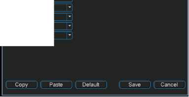 Figure 4-28 After all the setting please click save button. In one window display mode, right click mouse (click Fn Button in the front panel or click Fn key in the remote control). The interface is shown as in Figure 4-29.  fnlitliliWHiiW Color Setting Search Record Alarm Output Alarm Input Main Menu Figure 4-29 Click Pan/Tilt/Zoom, the interface is shown as below. See Figure 4-30. Here you can set the following items: Step: value ranges fro 1 to 8. Zoom Focus iris Click icon Ы and У to adjust zoom, focus and iris. PANILT/ZOOM Speed [Pige Switch Zoom Ф Focus Ф Iris Ф [iPtz Trace] Figure 4-30 In Figure 4-30, please click direction arrows (See Figure 4-31) to adjust PTZ position. There are total 8 direction arrows.  Figure 4-31 4.8.3 3D Intelligent Positioning Key In the middle of the eight direction arrows, there is a 3D intelligent positioning key. See Figure 4-32. Click this key, system goes back to the single screen mode. Drag the mouse in the screen to adjust section size. It can realize PTZ automatically.  Figure 4-32 Here is a sheet for you reference.
4.9 Preset/ Patrol/Pattern/Scan In Figure 4-30, click the set button. The interface is shown as below. See Figure 4-33. Here you can set the following items: Preset Tour Pattern Border PAN/TILT/ZOOM Function Preset Tour Pattern Border Preset 1 Patrol No. 0 Del Preset Figure 4-33 In Figure 4-30, click page switch button, the interface is shown as in Figure 4-34. Here you can activate the following functions: Preset Tour Pattern Auto scan Auto pan Flip Reset Page switch No. o AutoScan [Page Switch] AutoPan Figure 4-34 Note: The following setups are usually operated in the Figure 4-30,Figure 4-33 and Figure 4-34 . 4.9.1Preset Setup In Figure 4-30, use eight direction arrows to adjust camera to the proper position. In Figure 4-33, click preset button and input preset number. The interface is shown as in Figure 4-35. Now you can add this preset to one tour. PAN/TILT/ZOOM Function Preset Tour Pattern  Patrol No. \0 Del Preset Figure 4-35 4.9.2 Activate Preset In Figure 4-34, please input preset number in the No. blank, and click preset button. 4.9.3 Patrol setup (Tour Setup) In Figure 4-33, click patrol button. The interface is shown as in Figure 4-36.Input preset number and add this preset to a patrol (tour). For each patrol (tour), you can input max 80 presets. 1 PAM/TILT/ZOOM Xj Function Preset Pattern Border I Patrol No. 0 I Add PreseT г Del PreseT Figure 4-36 4.9.4 Activate Patrol (tour) In Figure 4-33, input patrol (tour) number in the No. blank and click patrol button 4.9.5 Pattern Setup In Figure 4-33, click pattern button and then click begin button. The interface is shown as in Figure 4-37. Then you can go to Figure 4-30 to modify zoom, focus, and iris. Go back to Figure 4-37 and click end button. You can memorize all these operations as pattern 1. I PANrriLT/ZOOM X \ Function Pattern l P Patrol No. [гп Patrol L-1 Pattern 1 I Begin Border (l End 4.9.6 Activate Pattern Function In Figure 4-34, input mode value in the No. blank, and click pattern button. 4.9.7 Auto Scan Setup In Figure 4-33, click border button. The interface is shown as in Figure 4-28. Please go to Figure 4-30, use direction arrows to select camera left limit Then please go to Figure 4-38 and click left limit button Repeat the above procedures to set right limit. 1ф PAM/TILT/ZOOM xl Function Pattern l Patrol No. [0 I Patrol - Pattern t Left 1  Figure 4-38 4.9.8 Activate Auto Scan In Figure 4-34, click Auto Scan button, the system begins auto scan. Correspondingly, the auto scan button becomes to stop button. Click stop button to terminate scan operation. 4.10 Flip In Figure 4-34, click page switch button, you can see an interface is shown as below. See Figure 4-39. Here you can set auxiliary function. Click page switch button again, system goes back to Figure 4-30. 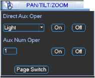 Figure 4-39 5 Understanding of Menu Operations and Controls 5.1 Menu Tree This series DVR menu tree is shown as below. 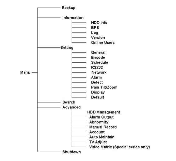 5.2 Main Menu After you logged in, the system main menu is shown as below. See Figure 5-1 . There are total six icons: search, Information, setting, backup, advanced and shutdown. Move the cursor to highlight the icon, then double click mouse to enter the sub-menu. 1 2 3 4 5 6 7 8 ... 14 |