
8(903)201-21-74
ООО "ЧетыреДатчика"
|
Оператор: 8(903)201-21-74 ООО "ЧетыреДатчика" |
|
Оператор: 8(903)201-21-74 ООО "ЧетыреДатчика" |
Главная страница Dvr features and function 1 ... 3 4 5 6 7 8 9 ... 14 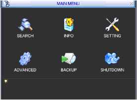 Figure 5-1 5.3 Setting In main menu, highlight setting icon and double click mouse. System setting interface is shown as below. See Figure 5-2. ЩЖ SETTING X I GENERAL ENCODE SCHEDULE RS232 NETWORK С i О ALARM DETECT PANn ILT/ZOOM DISPLAY DEFAULT Figure 5-2 5.3.1 General General setting includes the following items. See Figure 5-3. System time: here is for you to set system time Date format: there are three types: YYYYY-MM-DD: MM-DD-YYYYY or DD-MM- YYYY. Date separator: there are three denotations to separate date: dot, beeline and solidus. Snapshoot: Here you can set image upload interval. (This function applies to some series only). DST: Here you can set DST time and date. Please enable DST function and then click set button. You can see an interface is shown as in Figure 5-4. Here you can set start time and end time by setting corresponding week setup. In Figure 5-4, enable date button, you can see an interface is shown as in Figure 5-5. Here you can set start time and end time by setting corresponding date setup. Time format: there are two types: 24-hour mode or 12-hour mode. Language: system supports various languages: Chinese (simplified), Chinese (Traditional), English, Italian, Japanese, French, Spanish (All languages listed here are optional. Slight difference maybe found in various series.) HDD full: Here is for you to select working mode when hard disk is full. There are two options: stop recording or rewrite. Pack duration: Here is for you to specify record duration. Default value is 60 minutes. DVR No: when you are using one remote control to control several DVRs, you can give a name to each DVR for your management. Video standard: There are two formats: NTSC and PAL. Auto logout: Here is for you to set auto logout interval once login user remains inactive for a specified time. Value ranges from 0 to 60 minutes. Note: Since system time is very important, do not modify time casually unless there is a must! After completing all the setups please click save button, system goes back to the previous menu. GENERAL System Time (2008 - 05 - 05 114 : 20:: 29  Date Format (YYYY MM DD( Date Separator - Time Format (24-HOUR Language ( ENGLISH R Snapshot HDD Full (ENGLISH Overwrite Pack Duration 60 DVR No. [8 Video Standard (PAL Auto Logout fTo Default Cancel Figure 5-3 Day of Week О Date Stan: jun -( (1st End: Sep -( (1st - Sun H 00 : 00 00 : 00 Cancel о Day of Week Date Start: Щ|2008 - 06 - 01 00 : 00 End: Щ|2008 - 09 - 01 00 : 00 Figure 5-5 5.3.2 Encode Encode setting includes the following items. See Figure 5-6. Please note some series do not support extra stream. Channel: Select the channel you want. Compression: system supports H.264. Or you can select from the dropdown list. Resolution: System supports various resolutions, you can select from the dropdown list. For this model, we can support D1/CIF. Bit rate: system supports two types: CBR and VBR. In VBR mode, you can set video quality. Quality: There are six levels ranging from 1 to 6. The sixth level has the highest image quality. Frame rate: there are six levels: 1 f/s,2f/s,3f/s, 6f/s,12f/s,25f/s. (Some series DVRs only support PAL 25f/s ) Video/audio: you can enable or disable the video/audio respectively for the main stream and extra stream. Overlay: click overlay button, you can see an interface is shown in Figure 5-7. Cover area (Privacy mask): Here is for you to set window blanking section. You can drag you mouse to set proper section size. Preview/monitor: privacy mask has two types. Preview means the privacy mask zone can not be viewed by user when system is in preview status. Monitor means the privacy mask zone can not be view by the user when system is in monitor status. Time display: You can select system displays time or not when you playabck. Channel display: You can select system displays channel number or not when you playback. Snapshoot: Click snapshoot button, you can see an interface is shown as in Figure 5-8.(This function applies to some series only) Mode: There are two types: one is timing and the other is activation (trigger). Image size: D1/HD1/BCIF/CIF. Image quality: level1 to level 6. Snapshoot frequency: Here you can set the snapshoot frequency. The value ranges from 1s/p to 7s/p. System default setup is: Channel:1 Compression:H.264 Resolution: CIF/D1 Bit rate: CBR Quality: 4 Frame rate: 25f/s Please highlight icon = to select the corresponding function. ENCODE Channel 1 Compression H.264 Resolution CIF Bit Rate Type CBR Bit Rate(Kb/S) 512 - Frame Rate 25 Max Bit Rate 480-760Kb/S Audio/Video Щ Щ I OVERLAY ((SNAPSHOT] Extra Stream Ih- 256-512Kb/S Figure 5-6 OVERLAY Cover-Area ( Preview ( Monitor Time Display Channel Display Monitor Monitor Figure 5-7 SNAPSHOT Mode (Timing Image Size (D1 Image Quality (4 Snapshot Frequency (1 SP2L  Figure 5-8 For HBE-S series, it supports various settings for channel, resolution and frame: Resolution: pixel PAL: QCIF=176x144; CIF = 352x288; HD1 =352576; 2CIF=704x288; D1 =704x576; NTSC: QCIF=176x120; CIF = 352x240; HD1 =352x480; 2CIF=704x288; D1 =704x480; We take 16-channel DVR as an example. There are four groups: 1~4, 5~8, 9~12, 13~16. Please refer to the formula: resolutionX frame rate The resources for one group are: PAL: D1x50 or NTSC: D1x60 D1x50(60)F/s=Half-D1x100(120)F/s=CIFx200(240)F/s You can arrange channel parameter within the specified limit. Please refer to the following list:
Note: A> B> C> D is the four channels in one group. The totally whole resources are limited. When you wan to enhance resource in one channel you need to reduce resource for other channel. The system will pop up setup failure interface if the resource setup is beyond the limit. In the above list, x means there is no video in current channel. You can highlight video button to activate video function. Dual encoding streams: this series support dual encoding streams. Main stream is for local recording, and the extra stream can be used for network transmission. And they dont affect each other. So for local recording you can use main stream. And for network transmission, you can select main stream or extra stream. 5.3.3 Schedule Please refer to chapter 4.4 schedule. 5.3.4 RS232 RS232 interface is shown as below. Here are five items. See Figure 5-9.
Function: There are various devices for you to select. Console is for serial port or min-end platform to upgrade program. Keyboard is for you to use special keyboard to control current device. Baud rate: You can select proper baud rate. Data bit: You can select proper data bit. Stop bit: There are three values: 1/1.5/2. Parity: there are three choices: none/odd/even. After completing all the setups please click save button, system goes back to the previous menu. 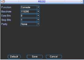 Figure 5-9 5.3.5 Network Here is for you to input network information. See Figure 5-10. IP address: Here you can input IP address. DHCP: It is auto search IP function. When enable DHCP function, you can not modify IP/Subnet mask /Gateway. These values are from DHCP function. If you have not enabled DHCP function, IP/Subnet mask/Gateway display as o. You need to disable DHCP function to view current IP information. Besides, when PPPoE is operating, you can not modify IP/Subnet mask /Gateway. TCP port: Default value is 37777. (System server port 37778 is reserved for network UDP use.) UDP port: Default value is 37778. HTTP port: Default value is 80. Max connection: system support maximal 10 users. 0 means there is no connection limit. Transfer mode: Here you can select the priority between fluency/video qualities. Network download: System can process the downloaded data first if you enable this function. After completing all the setups please click save button, system goes back to the previous menu. NETWORK IP Address ИэГ Subnet Mask 125Г 1 . 108 I 255 . 0 1 1 I I HTTP Port DHCP Gateway 192 168 1 -1 TCP Port [l ] HTTP Port R UDP Port 0 I Max Connection fo Q Transfer Mode [Fluency ~ I I Network Download ADVANCED SETTING П IP FILTER Trusted Sites:0 □ NTP 0.0.0.0:10 □ MULTICAST 239.255.42.42 0 PPPOE username Figure 5-10 5.3.5.1 Advanced Setup Advanced setup interface is shown as in Figure 5-11. Please draw a circle to enable corresponding function and then double click current item to go to setup interface. 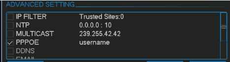 Figure 5-11 5.3.5.2 IP Filter IP filter interface is shown as in Figure 5-12. You can add IP in the following list. The list supports max 64 IP addresses. Please note after you enabled this function, only the IP listed below can access current DVR. If you disable this function, all IP addresses can access current DVR. 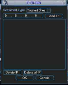 Figure 5-12 5.3.5.3 Multiple Cast Setup Multiple-cast setup interfacejs shown as in Figure 5-13. MCAST SET 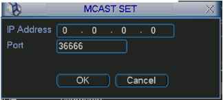 Figure 5-13 Here you can set a multiple cast group. Please refer to the following sheet for detailed information. IP multiple cast group address -224.0.0.0-239.255.255.255 - D address space The higher four-bit of the first byte= 1110 Reserved local multiple cast group address -224.0.0.0-224.0.0.255 -TTL=1 When sending out telegraph -For example 224.0.0.1 All systems in the sub-net 224.0.0.2 All routers in the sub-net 224.0.0.4 DVMRP router 224.0.0.5 OSPF router 224.0.0.13 PIMv2 router Administrative scoped addressees -239.0.0.0-239.255.255.255 -Private address space Like the single broadcast address of RFC1918 Can not be used in Internet transmission Used for multiple cast broadcast in limited space. Except the above mentioned addresses of special meaning, you can use other addresses. For example: Multiple cast IP: 235.8.8.36 Multiple cast PORT: 3666. 5.3.5.4 PPPoE PPPoE interface is shown as in Figure 5-14. Input PPPoE name and PPPoE password you get from your ISP (Internet service provider). Click save button, you need to restart to activate your configuration. After rebooting, IP camera will connect to internet automatically. The IP in the PPPoE is the DVR dynamic value. You can access this IP to visit the unit. User Name Password IP Address I 0 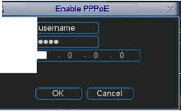 Figure 5-14 5.3.5.5 NTP Setup You need to install SNTP server (Such as Absolute Time Server) in your PC first. In Windows XP OS, you can use command net start w32time to boot up NTP service. NTP setup interface is shown as in Figure 5-15. Host IP: Input your PC address. Port: This series DVR supports TCP transmission only. Port default value is 123. Update interval: minimum value is 15(Unit: minute) Time zone: select your corresponding time zone here. Here is a sheet for your time zone setup.
HostIP Port TimeZone Update Period 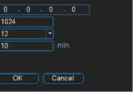 Figure 5-15 5.3.5.6 Email Setup Email setup interface is shown as in Figure 5-16. Here you can set email server information. Note: You need to get the email address from your email service provider first. Please use semicolon to separate the addresses. IP Address Port User Name Password Sender Title Receiver dvr@163.com .DVREmail Effective Time Q 00 :00 □ loo :00 Figure 5-16 5.3.5.7 DDNS Setup DDNS setup interface is shown as in Figure 5-17. You need a PC of fixed IP in the internet and there is the DDNS software running in this PC. In other words, this PC is a DNS (domain name server). In network DDNS, input your PPPoE name you get from you IPS and server IP (PC with DDNS ) . Click save button and then reboot system. Click save button, system prompts for rebooting to get all setup activated. After rebooting, open IE and input as below: http: (DDNS server IP)/(virtual directory name)/webtest.htm e.g.: http: 10.6.2.85/DVR DDNS/webtest.htm.) Now you can open DDNSServer web search page. 1 ... 3 4 5 6 7 8 9 ... 14 |
|||||||||||||||||||||||||||||||||||||||||||||||||||||||||||||||||||||||||||||||||||||||