
8(903)201-21-74
ООО "ЧетыреДатчика"
|
Оператор: 8(903)201-21-74 ООО "ЧетыреДатчика" |
|
Оператор: 8(903)201-21-74 ООО "ЧетыреДатчика" |
Главная страница Dvr features and function 1 ... 5 6 7 8 9 10 11 ... 14 5.5.7 TV Adjust Here is for you to adjust TV output setup. See Figure 5-36. Please drag slide bar to adjust each item. After all the setups please click OK button, system goes back to the previous menu. TV ADJUST Top Deflate Bottom Deflate Lett Deflate Righit Deflate Brigfitness Figure 5-36 5.5.8 Video Matrix (For HBEH~S and HBEL-S Series only) Some series DVR have the matrix and loop outputs. 5.5.8.1 Loop outputs They are just the same with video distributors. There are 4/8/16-ch video loop outputs from our DVR. The DVR video output can connect with other devices such as TV walls, analog matrix and so on. 5.5.8.2 Matrix outputs They are like the small-scale matrix. You can select any camera from our DVR to switch. And the output can also tour between the cameras. So the matrix outputs can be used to build TV walls and tour and display the cameras one by one. 5.5.8.3 Rear Panel Connection The rear panel is shown as below. See Figure 5-37. Connect to 37-pin cable 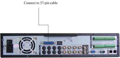 Figure 5-37 5.5.8.4 37-pin cable introduction There are three colors cable. See Figure 5-38. Black: for loop outputs, there are 16-ch loop outputs Blue: for matrix outputs, there are 4-ch matrix outputs White: for bi-direction talk, one is for audio in and the other is for audio out. 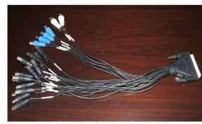 Figure 5-38 5.5.8.5 Matrix setup 5.5.8.5.1 Enter Video Matrix Interface In the menu, from Advanced to Video Matrix . You can see an interface is shown as in Figure 5-39. IP ADVANCED xl ALARM INPUT HDD MANAGEMENT ALARM OUTPUT MANUAL RECORD ACCOUNT AUTO MAINTAIN TV ADJUST VIDEO MATRIX Figure 5-39 5.5.8.5.2 Right Mouse Menu In one-window display mode, right click mouse to select Video Matrix . See Figure 5-40. РапЛ ! It/Zoom Cpjor Setting Alarm Output Alarm Input VideOMatrix Main Menu Figure 5-40 5.5.8.6 Video Matrix Interface and Application The video matrix interface is shown as in Figure 5-41. Now HBEL-S series support 4-channel matrix outputs and HBEH-S series support 1 channel matrix output. All the operation below based on HBEL-S series DVR. You can set for each channel. The function consists of three types. The priority is: alarm>motion detection>schedule. 5.5.8.6.1 Scheduled Video Output (Scheduled Tour) Please enable corresponding video output item and input tour interval, and then set the tour output channel. System maximally supports 16 channels. Now system can implement tour output as you just set. hHeigrehlighted cSaenleccetl ALL or hSeerleect channel(s) IlSo. Video Output 1 @В В В □ В Input interval here □ Video Output 2 ЁРШИШИИВшМВИННЙЕВа Interval 5 sec. □ Video Output 3 0Ш(1ЩШЩ(Ю(1 о и ш 000000 Interval 5 sec. □ Video Output 4 еШШЩИЩС D ш ш ш ш J000S Interval [5 sec. Note:The linkage setting of Alarm and Motion Detect is in the page of ALARM and DETECT (г Default Save Cancel 1 Figure 5-41 5.5.8.6.2 Alarm Activation Matrix Please go to alarm setup interface to set the alarm activate matrix function ((Main Menu->Setting->Alarm)). See Figure 5-42. You can follow the steps listed below: Select local alarm The record channel function has been enabled and you have selected corresponding record channel. The video matrix function has been enabled and you have selected corresponding video matrix channel. After selecting activation channel in the record channel item, you can enable video matrix function and then select vide output channel. Once the alarm occurs, system continues scheduled matrix tour after alarm tour completes. If there is no scheduled tour available, the matrix will stop at the last activation channel after alarm completes. When several alarm input at the same time, the situation maybe a little bit complex. Here is an example. System setup is shown as below: Alarm input 1 can activate channel1/2/3/4/5/6 Alarm input 2 can activate channel 2/3/4/5/6/7/8 Alarm input 1 and alarm input 2 activate video output 1. So, when there is alarm from channel 1, video output 1 becomes valid. If there is no alarm from alarm input 2 during the same period, then video output 1 can tour between channel1/2/3/4/5/6. When video output 1 goes to channel 3 and there is alarm form channel2, then video output 1 tour between 4/5/6/7/8/2. The general principles are: When alarm activate, each valid channel alarm input can activate a complete tour between activation channels. When there are several alarm inputs in the same video matrix output, system video matrix can activate all the channels in the setup. If system has toured some activation channels, then corresponding alarm activation channels are null. Event Type Enable Local Alarm Alarm In sriod у Set lAlut И© [lid )S(now Message Select alarm input channel □AIDut И©©!!]©® Latch 110 [see. Q3row Message QSend Email Record Channel Я[2][3][4](5](б][Т][1][1]ТдОВдЗИ03И □ PTZ Activation Select ] Delay 10 [sec. □Tour ВЕШИ©® □ Snapshot (2](3][4](5](6)(7 Video Matrix [ЦШЕ! Paste jifTiifrffTifratTg  Figure 5-42 5.5.8.6.3 Motion Detection (including video loss and camera masking) Motion detection principle is the same as alarm. You can set in motion detection interface (Main menu->Setting->Detect). See Figure 5-43. In detect interface, you can set the activation channel. You can enable video matrix function if you want to set matrix function, and then set video matrix output channel. Once the activation occurs, system continues scheduled matrix tour after motion detection tour completes. If there is no scheduled tour available, the matrix will stop at the last activation channel after alarm completes Event Type Enable Region Period □Alarm Out r~IShow Message Record Channel □ PTZ Activation □Tour Snapshot Video Matrix 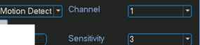 Select [□□□□(i] Latch □ Send Email [□□□□(SBog Select ) Delay [□□□□©□□(DOQS (2](3]Ш(5](6]Ш(1](9]ИО0 I 1 i Default ] ([ Savi Cancel Figure 5-43 5.5.8.6.4 General Tour Principle When system is in scheduled tout status, once the alarm occurs, system first check video matrix function has been enabled or not and there is effective matrix or not. System will continue implementing scheduled tour in the following two conditions: Video output function has not been enabled. There is no video matrix setup available. If there is valid video matrix setup, system can activate corresponding tour among alarm channels and then begin scheduled tour after alarm tour completes. If there is no schedule tour available, the matrix will stop at the last activation channel after alarm completes. Motion detection activation is almost the same as the alarm. But it has different priority. System will continue implementing scheduled tour in the following two conditions: Video output function has not been enabled. There is no video matrix setup available. If there is a valid video matrix setup, system will check weather there is tour of higher priority and implement corresponding process. During the motion detection tour, system will process alarm first if alarm occurs. It is the same as alarm occurs in scheduled tour period. 5.6 Information Here is for you to view system information. There are total five items: HDD (hard disk information), BPS (data stream statistics), Log and version, and online user. See Figure 5-44. 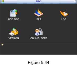 5.6.1 HDD Information Here is to list hard disk type, total space, free space, video start time and status. See Figure 5-45. Note: Please remove the broken hard disk before you add a new one. Once there is a hard disk confliction, please check hard disk time and system time is the same or not. Please go to setting then general to modify system time. At last, reboot the system to solve this problem. If disk is damaged, system shows as ? 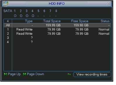 Figure 5-45 5.6.2 BPS Here is for you to view current video data stream (KB/s) and occupied hard disk storage (MB/h). See Figure 5-46. 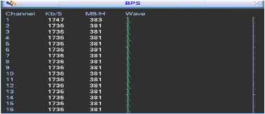 Figure 5-46 5.6.3 Log Here is for you to view system log file. System lists the following information. See Figure 5-47. Log types include system operation, configuration operation, data management, alarm event, record operation, log clear and etc. Pleased select start time and end time, then click search button. You can view the log files. Please page up/down button to view if there are more than ten files. 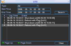 Figure 5-47 5.6.4 Version Here is for you to view some version information. See Figure 5-48. Channel Alarm in Alarm out System version: Build Date 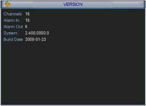 Figure 5-48 5.6.5 Online Users Here is for you manage online users. See Figure 5-49. You can disconnect one user or block one user if you have proper system right. 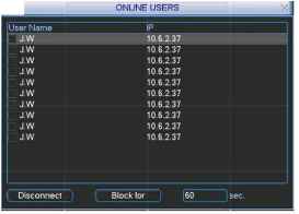 5.7 Exit Figure 5-49 Double click exit button, system pop up a dialogue box for you to select. See Figure 5-50. Logout menu user: log out menu. You need to input password when you login the next time. Restart application: reboot DVR. Shutdown: system shuts down and turns off power. Restart system: system begins rebooting. Switch user: you can use another account to log in. 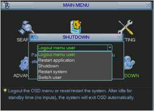 Figure 5-50 6 About Auxiliary Menu 6.1 Go to Pan/Tilt/Zoom Menu In the one-window surveillance mode, right click mouse (click fn Button in the front panel or click AUX key in the remote control). The interface is shown as below: See Figure 6-1. View 1 i View 4 View 9 View 16 Pan.TillZoom Color Setting Search Record Alarm Output Alarm Input Main Menu Figure 6-1 Click Pan/Tilt/Zoom, the interface is shown as in Figure 6-2. Here you can set the following items: Zoom Focus Iris Click icon У and У to adjust zoom, focus and Iris. 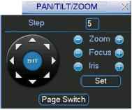 Figure 6-2 In Figure 6-2, please click direction arrows (See Figure 6-3 ) to adjust PTZ position. There are totally eight direction arrows. (Please note there are only four direction arrows in DVR front panel.)  6.1.1 3D Intelligent Positioning Key 1 ... 5 6 7 8 9 10 11 ... 14 |