
8(903)201-21-74
ООО "ЧетыреДатчика"
|
Оператор: 8(903)201-21-74 ООО "ЧетыреДатчика" |
|
Оператор: 8(903)201-21-74 ООО "ЧетыреДатчика" |
Главная страница Dvr features and function 1 ... 6 7 8 9 10 11 12 ... 14 In the middle of the eight direction arrows, there is a 3D intelligent positioning key. See Figure 6-4 . Click this button, system goes back to the single screen mode. Drag the mouse in the screen to adjust section size.  Figure 6-4 Here is a sheet for you reference.
6.2 Preset /Patrol / Pattern /Border Function In Figure 6-2 click the set button. The interface is shown as below: Here you can set the following items:
Preset Patrol Pattern Border PAN/TILT/ZOOM Function Preset jl j f Patrol No. [0~~ Patrol . =i Pattern I Set ) Border I Dei Preset Figure 6-5 In Figure 6-2, click page switch button, you can see an interface as in Figure 6-6. Here you can activate the following functions: Preset Tour(Patrol) Pattern Auto scan Auto pan Flip Page Switch PANmLT/ZOOM Preset
Flip Page Switcli Reset Figure 6-6 6.2.1 Preset Setup Note: The following setups are usually operated in the Figure 6-2, Figure 6-5 and Figure 6-6. In Figure 6-2, use eight direction arrows to adjust camera to the proper position. In Figure 6-5, click preset button and input preset number. The interface is shown as in Figure 6-7. Add this preset to one patrol number PAMrriLT/ZOOM x Function Preset Pf Patron Patrol Pattern CZ Border f. Patrol No. 0 ( Del Preset Figure 6-7 6.2.2 Activate Preset In Figure 6-6 please input preset number in the No. blank, and click preset button. 6.2.3 Patrol Setup In Figure 6-5, click patrol button. The interface is shown as in Figure 6-8. Input preset number and then add this preset to one patrol. PAN/TILT/ZOOM 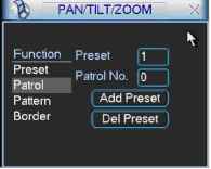 Figure 6-8 6.2.4 Activate Patrol In Figure 6-6, input patrol number in the No. blank and click patrol button 6.2.5 Pattern Setup In Figure 6-5, click pattern button and then click begin button. The interface shows like Figure 6-9. Please go to Figure 6-2 to modify zoom, focus, and iris. Go back to Figure 6-9 and click end button. You can memorize all these setups as pattern 1. I % PAM/TILT/ZOOM XJ Function Pattern Pf Patrol No. 1С Patrol Border li  Figure 6-9 6.2.6 Activate Pattern Function In Figure 6-6 input mode value in the No. blank, and click pattern button. 6.2.7 Border Setup In Figure 6-5, click border button. The interface is shown as in Figure 6-10. Please go to Figure 6-2, use direction arrows to select camera left limit, and then please go to Figure 6-10 and click left limit button Repeat the above procedures to set right limit. PAN/TILT/ZOOM Function Pattern Pf Patrol No. f Patrol [ Pattern 1 Left Border I fi Rinh o. [O I 1 Figure 6-10 6.2.8 Activate Border Function In Figure 6-6, click auto scan button, the system begins auto scan. Correspondingly, the auto scan button changes to stop button. Click stop button to terminate scan operation. 6.2.9 Flip In Figure 6-6, click page switch button, you can see an interface is shown as below. See Figure 6-11. Here you can set auxiliary function. Click page switch button again, system goes back to Figure 6-2. PANmLT/ZOOM Direct Aux Oper 3 Co foT] Aux Num Oper Page Switch ГогП ГоГ Figure 6-11 7 WEB CLIENT OPERATION Please note, all the operation here is taking 16-ch DVR as an example. There might be slightly difference in the interface due to different series. 7.1 Network Connection Before web client operation, please check the following items: Network connection is right DVR and PC network setup is right. Please refer to network setup(main menu->setting->network) Use order ping ***.***.***.***(* DVR IP address) to check connection is OK or not. Usually the return TTL value should be less than 255. System is compatible with WIN VISTA web control right now. But you need to disable user account control function. Double click user account and then disable user account control. After completing setup, please reboot the PC. System can automatically download latest web control and the new version can overwrite the previous one. If you want to un-install the web control, please run uninstall web.bat. Please note, before you un-install, please close all web pages, otherwise the un-installation might result in error. 7.2 Login Open IE and input DVR address in the address column. For example, if your DVR IP is 10.10.3.16, then please input http: 10.10.3.16 in IE address column. See Figure 7-1
Figure 7-1 System pops up warning information to ask you whether install webrec.cab control or not. Please click yes button. If you cant download the ActiveX file, please modify your settings as follows. See Figure 7-2. Security Settings - Internet Zone 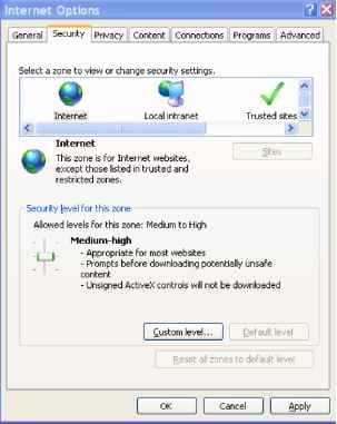 Setting; c) Disable @ Enable Download signed ActiveX controls (not secure) О Disable © Enable (not secure) О Prompt (recommended) Download unsigned ActiveX controls (not secure) О Disable (recommended) © Enable (not secure) О Prompt Initialize and script ActiveX controls not marked as safe for si О Disable (recommended) © Enable (not secure) О Prompt [j] Run ActiveX controls and plug-ins *Takes effect after you restart Internet Explorer Reset custom settings Reset to Medium-higfi (default) Reset... Cancel Figure 7-2 After installation, the interface is shown as below. See Figure 7-3. Please input your user name and password. Default factory name is admin and password is admin. Note: For security reasons, please modify your password after you first login. 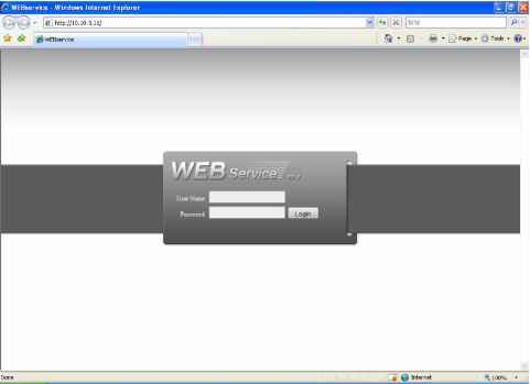 After you logged in, you can see the main window. See Figure 7-6. This main window can be divided into the following sections. Section 1: there are five function buttons: configuration (chapter 7.3), search (chapter 7.4), alarm (chapter 7.5), about (chapter 7.6), log out (chapter 7.7). Section 2: there are channel number and three function buttons: refresh, start dialog and local play. Section3: there are PTZ (chapter 7.2.2), color (chapter 7.2.3) button and you can also select picture path and record path. Section 4:real-time monitor window. Please note current preview window is circled by a green rectangle zone. Section 5: Here you can view window switch button. You can also select video priority between fluency or real-time. System monitor window switch supports full screen/1-window/4-window/6-window/8-window/9-window/13-window/16-window/20-window/25-window/36-window. See Figure 7-4. ш к □ ш h a h] [25] [361 Figure 7-4 Preview window switch. System support 1/4/8/9/16-window real-time preview. Please you need to have the proper rights to implement preview operation. You can not preview if you have no right to preview the either channel. See Figure 7-5. Figure 7-5 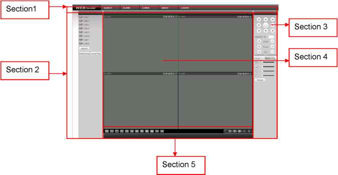 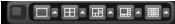 Figure 7-6 7.2.1 Real-time Monitor In section 2, left click the channel name you want to view, you can see the corresponding video in current window. For detailed function key information, please refer to Figure 7-7. i U i 1 i 1 2 3 4 5 6 Figure 7-7 1: Digital zoom: Click this button and then left drag the mouse in the zone to zoom in. right click mouse system restores original status. 2: Change show mode: resize or switch to full screen mode. 3: Local record. When you click local record button, the system begins recording and this button becomes highlighted. You can go to system -.local record to set video file path. 4: Capture picture. You can snapshoot important video. All images are memorized in system client folder \download\picture (default). 5: Audio :Turn on or off audio.(It has no relationship with system audio setup ) 6: Close video. Please refer to Figure 7-8 for main stream and extra stream switch information. 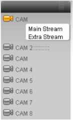 Figure 7-8 Refresh You can use button to refresh camera list. Start Dialogue You can click this button to enable audio talk. Local Play Click local play button, system pops up the following interface for you to select local play file. See Figure 7-9. 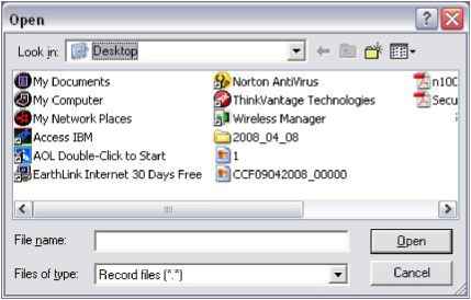 Figure 7-9 7.2.2 PTZ Before PTZ operation, please make sure you have properly set PTZ protocol. (Please refer to chapter 7.3.2 Setting-> Pan/Tilt/Zoom). Click PTZ button, the interface is shown as in Figure 7-10 . 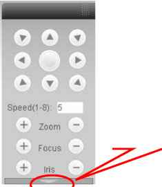 You can click this icon to display or hide the PTZ control platform. Figure 7-10 7.2.2.1 Direction key and 3D positioning key In Figure 7-10, there are eight direction keys. In the middle of the eight direction keys, there is a 3D intelligent positioning key. Click SIT button, system goes back to the single screen mode. Drag the mouse in the screen to adjust section size. It can realize PTZ automatically. 7.2.2.2 Speed System supports eight-level speed. You can select from the dropdown list. Speed 2 is faster than speed 1. 7.2.2.3 Zoom/Focus/Iris Here is a sheet for you reference.
Then click triangle icon in Figure 7-10, you can see the following interface. See Figure 7-11. 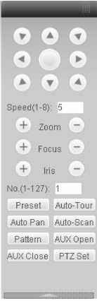 Figure 7-11 In Figure 7-11, click PTZ setup button you can see the following interface. See Figure 7-12. 1 ... 6 7 8 9 10 11 12 ... 14 |
|||||||||||||||||||||||||||||||||||||||||||||||||||||||||||||||||||||||||||||||||||||||