
8(903)201-21-74
ООО "ЧетыреДатчика"
|
Оператор: 8(903)201-21-74 ООО "ЧетыреДатчика" |
|
Оператор: 8(903)201-21-74 ООО "ЧетыреДатчика" |
Главная страница Dvr following and features 1 ... 8 9 10 11 12 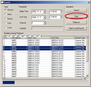 Figure 7-57 7.5 Alarm Here you can set alarm type and alarm prompt audio file. See Figure 7-58. 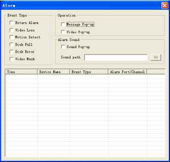 Figure 7-58 7.6 About Click about button, you can view current web client information. See Figure 7-59.  Figure 7-59 7.7 Log out Click log out button, system goes back to log in interface. See Figure 7-60. 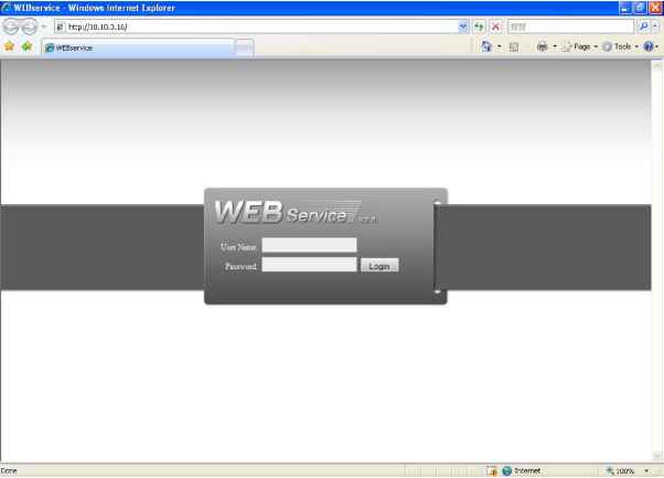 Figure 7-60 7.8 Un-install Web Control You can use web un-install tool uninstall web.bat to un-install web control. Please note, before you un-installation, please close all web pages, otherwise the un-installation might result in error. 8 Enterprise Professional Surveillance System In this chapter, we introduce how to add devices and how to enable monitor function. For detailed operation, please refer to enterprise professional surveillance system users manual. 8.1 Log in Double click enterprise profession surveillance platform icon ( ).lf it is your first time to use the system, you can see the following interface. See Figure 8-1. 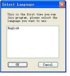 Figure 8-1 After selecting a language, you can see the following interface. Here you can input user name and password to log in you selected server. The log in interface is shown as in Figure 8-2. If it is your first time to use the system, you need to click add button to add a device first. Default central control server name is Local. System default username and password both are admin. Note: For security reasons please modify your password after you first logged in. 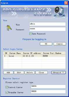 Figure 8-2 8.2 Enable Monitor After successfully logged in, please select the device and then click connect/disconnect button (®) . Select the channel you wan to view, click connect/disconnect button ( ) again. Section 1 Section 2
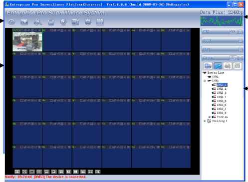 Section 5 Section 6 Figure 8-3 There are totally six sections: Section 1: There are eight function keys: monitor, E-map, record, save, alarm, configuration, log and system. Section 2: Here is for you to view channel video. Section 3: Here is for you to select display mode. System supports various display modes. HD item is for you to select priority between real-time and video fluency. Section 4: Here is for you to view current help information. Section 5: Here is to display data flux and CPU status. Section 6: There are four function buttons: PTZ, color, device, and plan. Please note system only supports one window in full-screen. Here we recommend resolution 1024*768. Select a device name and then click connect/disconnect button, you can connect current device to network. You can see a little red -cross below the name disappeared. Click one window on you left side and then double click channel name on you right hand, you can see the corresponding video in current window. Please refer to Figure 8-4 for connection/disconnection information.  Figure 8-4 8.3 Add New Device Click configuration button, you can see a network management unit shown as in Figure 8-5. There are five function buttons, from left to right: device management, user manager, E-map, device configuration and upgrade. f Het Manager niiit¥er4. 6. 0. 0 (build 2008-03-26) (IlnKesister) Building 1 Device List Device Name IF Address Fort ITumber User Heme Channel Amount DVI£ DVT3 DVK 10.10.3.16 3TTT7 60 19194 122 3TTTT 10.10.5.80 3TTT7 admin admin Add Edit Delete Add organization structure Add device Device List DVE2 DVK3 El Euilding 1 Export Import Add Edit Delete Figure 8-5 9 RS232 Operation 9.1 Network Connection Before serial port operation, please connect matrix with DVR through RS232. Then set DVR serial port protocol to the corresponding matrix protocol. Note: please contact you local retail to confirm the DVR supports matrix protocol or not. 9.2 Keyboard Control keyboard is very convenient for multi-DVR control, menu options and PTZ control. Select keyboard control from system Setting>RS232 > Function, and then set concerning attributes such as protocol. Connect DVR RS232 port to shifter 25-pin RS232 port and then set proper control addresses for all connected DVRs. Now you can input DVR control address and use keyboard keys to set menu or control PTZ. See Figure 9-1. Note: The keyboard works only when ACT light is on. 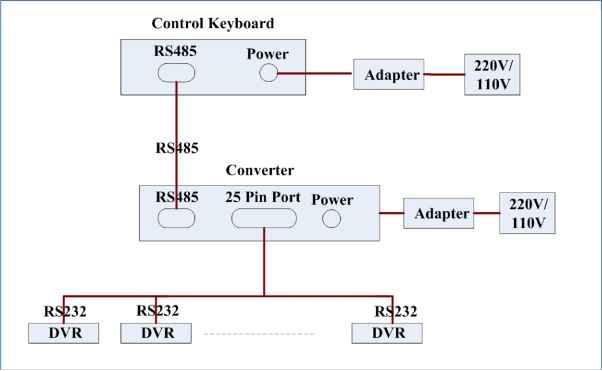 Figure 9-1 10 FAQ 1. This system can run in windows 98 or not? Please install DIRECTX 7.0 or higher manually if you want to run this system in windows 98 environment. 2. System can not detect hard disk. First check whether the hard disk is broken. Then check jumper, IDE data cable and power cord. Please make sure they are appropriately connected. When only one hard disk is connected to an IDE interface, this hard disk has to be jumped to master disc. 3. I can not use schedule recording function. Please note the recording time unit takes one day as a working unit. E.g.: from 0 oclock to 24 oclock. 4. Recording light is flashing during the whole recording procedure. Check the external video input signal. Such phenomena usually happen when the inputting signal is not standard. Sometimes reading speed of HD is too slow, this phenomenon occurs. In this situation, you need to change hard disk. 5. My DVR is very hot, is there any problem? DVR running procedures will generate a considerable hot. It is a normal phenomenon. Please note DVR installation environment should be dry and clean. Keep ventilation openings smooth. Otherwise it will reduce system stability and lifelong 6. I can not see video signal on one channel while the other channels are ok Check the video cable connection. You can connect camera video cable directly to monitor to test. If there is still no signal, there may be a problem with camera or video cable. If there is a video signal please contact your local suppliers for help. 7.I can not use my remote controller. Check ACT light on the front panel is on or not. ATC light is on: You need to change you remote controller battery. Act light is off: Please move remote controller directly to the DVR, and then press address button. System pops up address input dialogue box. Please input you remote address (default value is 008). When act light is on, you can use it now 8.I can not control PTZ or dome Check connection is right or not Check system setup. Please refer to 5.3.8 pan-tilt setup. Protocol should conform to dome (PTZ) setup. Protocol is matched or not. You can contact you local supplier for more information 9. I can not login via web There are two conditions: Network connection failure Check your DVR and PC connection is right or nor. Please check DVR IP, network cable or use order ping to check. Invalid password or username 10. At the first beginning, the surveillance video is poor when I connected to server. If the image can return to normal in five seconds, this phenomena is normal 12. What peripheral equipment DVR can work with? DVR supports much peripheral equipment such as keyboards matrix> control decode card.> alarm input and output equipments alarm server and access control system. Slight difference may be found in user interface. All the designs and software here are subject to change without prior written notice. Please visit our website for more information. Appendix A HDD Capacity Calculation Calculate total capacity needed by each DVR according to video recording (video recording type and video file storage time). Step 1: According to Formula (1) to calculate storage capacity that is the capacity of each channel needed for each hour, unit Mbyte. = 8 X 3600 1024 (1) In the formula: means the bit rate, unit Kbit/s Step 2: After video time requirement is confirmed, according to Formula (2) to calculate the storage capacity , which is storage of each channel needed unit Mbyte. = X X д (2) In the formula: h, means the recording time for each day (hour) means number of days for which the video shall be kept Step 3: According to Formula (3) to calculate total capacity (accumulation) qT that is needed for all channels in the DVR during scheduled video recording. In the formula: c means total number of channels in one Step 4: According to Formula (4) to calculate total capacity (accumulation) qT that is needed for all channels in DVR during alarm video recording (including motion detection). qT =m, xa% (4) In the formula: a% means alarm occurrence rate 1 ... 8 9 10 11 12 |