
8(903)201-21-74
ООО "ЧетыреДатчика"
|
Оператор: 8(903)201-21-74 ООО "ЧетыреДатчика" |
|
Оператор: 8(903)201-21-74 ООО "ЧетыреДатчика" |
Главная страница Dvr following and features 1 2 3 4 5 ... 12 3 Installation and Connections Note: All the installation and operations here should conform to your local electric safety rules. 3.1 Check Unpacked DVR When you receive the DVR from the shipping agency, please check whether there is any visible damage to the DVR appearance. The protective materials used for the package of the DVR can protect most accidental clashes during transportation. Then you can open the box to check the accessories. Please check the items in accordance with the list on the warranty card. Finally you can remove the protective film of the DVR. 3.2 HDD Installation 3.2.1 Choose HDDs We recommend Seagate HDD of 7200rpm or higher. 3.2.2 Calculate HDD Size This series have no limit to HDD capacity. You can use 120G-750G HDD to guarantee higher stability. The formula of total HDD size is: Total Capacity (MB) = Camera Amount * Recording Hours * HDD Usage Per Hour (M/h) H.264 compression is ideal for standalone DVRs. It can save more than 30% HDD capacity than MPEG4. When you calculate the total HD capacity, you should estimate the average HDD capacity per hour for each channel. For example, for a 4-ch DVR, the average capacity of HDD usage per hour per channel is 200M/h. Now if you hope the DVR can record the video 12 hours each day for 30 days, the total capacity of HDDs needed is: 4 channels * 30 days * 12 hours * 200 M/h = 288G. So you need to install one 300G HDD or 2 160G HDDs. 3.2.3 HDD Installation Data ribbons, fastening screws and smart HDD shelf design are already provided in the accessories. Please follow the instructions below to install hard disk. 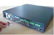 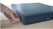 ©Dismantle the screws from the front and real panels. 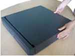 ©Remove the upper cover 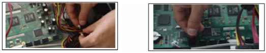 ©Unfasten the HDD power cable. ©Connect to data connection cable and then plug the HDD power cable. 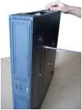 © Fix the HDD in the DVR. When installing HDD, please keep the side of the screw holes face down. 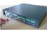 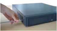 © Place the upper cover back and screw firmly. After HDD installation, please check connection of data ribbon and power cord. Note: For LN SATA series, the HDD ports are SATA and there is no need to set master/slave HDD. 3.3 CD/DVD Burner Installation For USB burners, you need to install USB series burner. This series DVR is compatible with various burner brands popular in todays market. You can consult our local technical support or visit our website for more information. 3.4 Desktop and Rack Mounting 3.4.1 Desktop Mounting To prevent surface damage, please make sure that the rubber feet are securely installed on the four corners of the bottom of the unit. Position the unit to allow for cable and power cord clearance at the rear of the unit. Be sure that the air flow around the unit is not obstructed. 3.4.2 Rack Mounting The DVR occupies two rack units of vertical rack space. The hardware necessary to mount the DVR into a rack is supplied with the unit. Rear doors may be used only on rack columns that are more than 26 inches (66.0 cm) deep. Install the cabinet in ventilated place. Avoid extreme heat, humid or dusty conditions. You can use a soft dry brush to clean opening outlet, cooling fan and etc regularly. 3.5 Connecting Power Supply Please check input voltage and device power button match or not. We recommend you use UPS to guarantee steady operation, DVR life span, and other peripheral equipments operation such as cameras. 3.6 Connecting Video Input and Output Devices 3.6.1 Connecting Video Input The DVR automatically detects the video standard (PAL or NTSC) whenever you connect a video input. It accepts both color and black-and-white and analog video. NOTE: Enabling line lock on cameras may cause video distortion. There may be noise in the cameras power source. If video from one or more cameras is distorted, we recommend you disable line lock on the camera as your first troubleshooting step. If a video distribution amplifier is installed between the video source and the DVR, do not set the output video level above 1 Vp-p. To connect each video input: 1. Connect a coaxial cable to the camera or other analog video source. 2. Connect the coaxial cable to the video in connector on the rear panel. Please refer to Figure 3-1 for more information. NOTE: You need to use a BNC installation tool to connect coaxial cables to the rear panel. Video Input I .i.i J-i--LJ-t- MjMjjji <jc ф'ф Ф ф ф ф ф Figure 3-1 3.6.2 Connecting Video Output This section provides information about physically connecting video display devices to the DVR. See Figure 3-2. If you connect the DVR with a TV monitor or VGA monitor, the DVR can automatically detects the monitor type. And without any output device, by default, the DVR is configured to use a TV monitor. In this case, if your application requires a VGA monitor, you have to press the button FN or Shift on the front panel,or restart the DVR. NOTE: Video output 1 and VGA cant display at the same time. But Video output 2 can display properly with Video Output 1 or VGA. 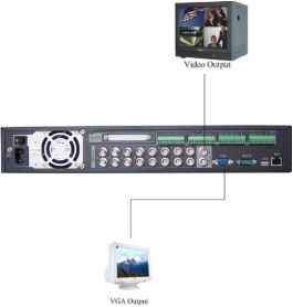 Figure 3-2 3.7 Connecting Audio Input & Output, Bidirectional Audio, Looping Video, Matrix For the 25-pin or 37-pin interface, different models include different functions. For example, DVR1604LNH-S has 4-channel audio inputs, 1 audio output, I bidirectional audio input. See Figure 3-3. Connect to 37-piti Cable -1 I I л' л pj. л + t w t m . luiMMM -121 1 ф ф ф ф ® ф% г^-ш^р^ьшм  3.7.1 Audio Input/One Audio Output DVR1604LNH-S has 16 looping video inputs, 1 matrix video output, 4 audio inputs, I bidirectional audio input, 1 audio output. Audio input, bidirectional audio input and audio output The DVR encodes audio and video signals simultaneously, which lets you control audio at the monitored location. To set up audio: 1. Make sure your audio input device matches the RCA input level. If the device and RCA input levels do not match, audio distortion problems may occur. 2. Make sure the audio connector is wired as follows: 3. Connect a line input device or pre-amplified microphone to the audio connector for the video channel on the rear panel. Please refer to Figure 3-4. Audio Output Audio Input ф 9 $ Щ Lli Figure 3-4 3.7.2 Looping video The DVR supports looping video. It passes the video input to a monitor or other analog video device. To use looping video: 1. Connect a coaxial cable to the video out connector on 37-pin interface Please note you need to use a BNC installation tool to connect coaxial cables to the rear panel. 2. Connect the other end of the coaxial cable to the analog device. 3.7.3 Matrix Video Output Use video matrix output connector during installation to display video sequentially from each video input. The unit displays each channel for selected seconds. You can use this feature to verify camera installation. To display video from each connected video source: 1. Connect a video monitor to the video matrix output connector. 2. Turn the DVR on, the monitor, and each video matrix output source. 3. Verify the video from each source and troubleshoot as necessary. Please refer to Figure 3-5. 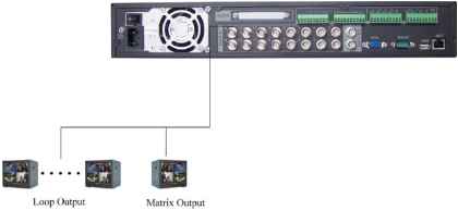 Figure 3-5 3.7.4 Alarm Input and Relay Output The DVR offers 16 alarm inputs for external signaling devices, such as door contacts or motion detectors. Each alarm input can be either normally open or normally closed. Once configured, an alarm input can invoke many different activities, including triggering a relay device, sending an alert to a security office or storing pre-alarm video to the DVR. 3.7.5 Alarm Input You should check your alarm input mode is grounding alarm input or not. For this series DVR, grounding signal is needed for alarm input. If you need to connect two units or one DVR and other device, please use relay to separate them. Please refer to Figure 3-6 for more information. A1 anil Input 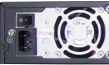 ЩКГ^шшт^ I \. MMd-ii jj j Figure 3-6 3.7.6 Alarm Output Do not connect alarm output port directly with high power load (no more than 1 A) in case of heavy current. You can use the co-contactor to realize the connection between the alarm output port and the load. Please refer to Figure 3-7 for more information. 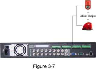 3.7.7 Alarm Input and Output Details You can refer to the following sheet and Figure 3-8 for alarm input and output information.
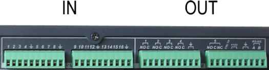 Figure 3-8 Please refer to the following content for alarm input port information. See Figure 3-9. 8/16-ch grounding alarm inputs. (Normal open or Normal close type) Please parallel connect COM end and GND end of the alarm detector (Provide external power to the alarm detector). Please parallel connect the Ground of the DVR and the ground of the alarm detector. Please connect the NC port of the alarm sensor to the DVR alarm input(ALARM) If you need to reset the touched-off alarm remotely, you can use DVR to supply controllable 12 V power to the alarm detector such as the smoke detector. Use the same ground with that of DVR if you use external power to the alarm device. 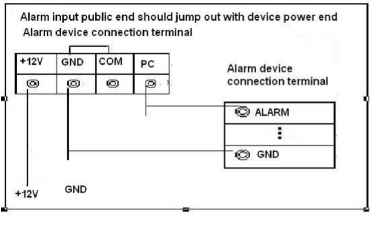 Figure 3-9 3.7.8 Relay Output Description 6 ways relay alarm output. Provide external power to external alarm device. To avoid over loading, please read the following relay parameters sheet carefully. (See below table) The controllable +12v can be used to restore the smoke detector. Please refer to Figure 3-10 for alarm input module information. 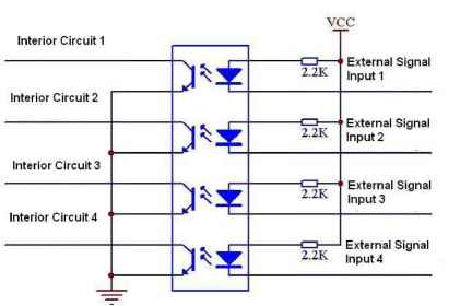 Figure 3-10 Please refer to Figure 3-11 for alarm output module information. 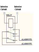 Figure 3-11 Relay Specification
3.8 RS232 You can connect the DVR with POS or Keyboard through RS232. With POS system, the DVR can communicate through RS232 and network. For the POS system, the DVR can integrate the text content and even search the record through the info. The series DVR also support NKB operation. You can operate the DVR from the keyboard controls instead of using the control pad on the front panel of the unit. To connect a NKB keyboard to the DVR: 1. Assemble the KBD keyboard according to the instructions in its accompanying installation manual. 2. Connect the KBD keyboard into one of the RS232 ports on the DVR or through network. 3.9 RS485 When the DVR receives a camera control command, it transmits that command up the coaxial cable to the PTZ device. RS485 is a single-direction protocol; the PTZ device cant return any data to the unit. To enable the operation, connect the PTZ device to the RS485(A,B) input on the DVR. Since RS485 is disabled by default for each camera, you must enable the PTZ settings first. This series DVRs support multiple protocols such as Pelco-D, Pelco-P. To connect PTZ devices to the DVR: 1. Connect RS485 A,B on the DVR rear panel. 2. Connect the other end of the cable to the proper pins in the connector on the camera. 3. Follow the instructions for configuring a camera to enable each PTZ device on the DVR. 3.10 Other Interfaces There are still other interfaces on the DVR, such as USB ports. You can refer to the Figure 3-12 for more information. 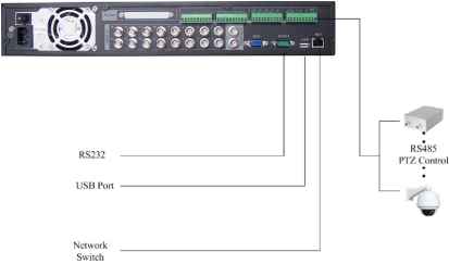 Figure 3-12 1 2 3 4 5 ... 12 |
||||||||||||||||||||||||||||||||||||||||||||||||||||||||||||||||