
8(903)201-21-74
ООО "ЧетыреДатчика"
|
Оператор: 8(903)201-21-74 ООО "ЧетыреДатчика" |
|
Оператор: 8(903)201-21-74 ООО "ЧетыреДатчика" |
Главная страница Dvr following and features 1 2 3 4 5 6 7 ... 12 Please highlight icon Я to select the corresponding function. After all the setups please click save button, system goes back to the previous menu. Note: In motion detection mode, you can not use copy/paste to set channel setup since the video in each channel may not be the same. In Figure 4-15, you can left click mouse and then drag it to set a region for motion detection. Click Fn to switch between deployment and withdraw motion detection. After setting, click enter button to exit. Ш DETECT ~n Channel 1 Type -Motion Detect * Record Channel и Ш m ® @ Ш d Latch flO I sec. Enable Tour D Region f Ptz Preset Sensitivity Alarm Out Q] (T] T] [T] [£] [б] Show Message Alarm Out Period 1 00:00 - 12:00 □ Period 2 [12:00 - 24:00 □ Paste Default Save Cancel Figure 4-14 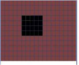 Figure 4-15
4.5.3 Video Loss In Figure 4-14, select video loss in the Type item. You can see the interface is shown as in Figure 4-17.This function allows you to be informed when video loss phenomenon occurred. You can enable alarm output channel and then enable show message function. Channel: select the channel you want to enable lens shading alarm. Type: please select video loss. Record channel: select the channel to record when video loss occurred. Alarm output: activate peripheral alarm device when video loss occurred. Enable tour: Here is for you to activate tour between different cameras. Latch: when motion detection completes, system auto delays detecting for a specified time. The value ranges from 10-300(Unit: second) PTZ preset: Click set button to set preset for one or all channels. See Figure 4-16. Period 1/2: It is for you to set two periods (00.00-24.00). Alarm output: when video loss occurred, system enables peripheral alarm devices. Please highlight icon to enable this function Show message: System pops up message in the screen to alert you once alarm occurred. Please highlight icon to enable this function. 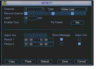 Figure 4-17 4.5.4 Camera Mask Detect When someone viciously masks lens, the system can alert you to guarantee video continuity. Camera mask detection interface is shown as in Figure 4-18. Channel: select the channel you want to enable camera mask detection function. Type: please select camera mask detect from the dropdown list. Record channel: select the channel to record when camera mask occurred. Alarm output: activate peripheral alarm device when camera mask occurred. Enable tour: Here is for you to activate tour between different cameras. Latch: when motion detection completes, system auto delays detecting for a specified time. The value ranges from 10-300(Unit: second) PTZ preset: Click set button to set preset for one or all channels. See Figure 4-16. Period 1/2: there are for you to set two periods (00.00-24.00). Alarm output: when camera masking occurred, system enables peripheral alarm devices. Please highlight icon to enable this function Show message: System pops up message in the screen to alert you once alarm occurred. Please highlight icon to enable this function Note: In this interface, copy/paste function is only valid for the same type, which means you can not copy a channel setup in video loss mode to camera mask detect mode. VM detect xl 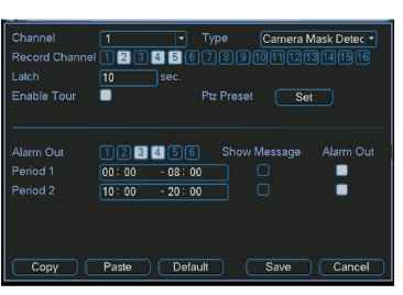 Figure 4-18 4.6 Alarm Setup and Alarm Activation Before operation, please make sure you have properly connected alarm devices such as buzzer. 4.6.1 Go to alarm setup interface In the main menu, from Setting to Alarm, you can see alarm setup interface. See Figure 4-19. 4.6.2 Alarm setup Alarm interface is shown as below. See Figure 4-19. Alarm in: here is for you to set channel number. Source of alarm: there are two alarm sources: local input or network input. Type: normal open or normal close. Record channel: you can select proper channel to record alarm video (Multiple choices). At the same time you need to set alarm record in schedule interface (Main Menu->Setting->Schedule) and select schedule record in manual record interface (Main Menu->Advance->Manual Record). Latch: Here is for you to set proper delay duration. Value ranges from 10 to 300 seconds. System automatically delays specified seconds in turning off alarm and activated output after external alarm cancelled. PTZ preset: Here is for you to activate PTZ control. Relay out: select proper alarm activation output channel (multiple choices). Show message: System pops up message in the screen to alert you once alarm occurred. Period 1 and period 2: set proper time and alarm tips.
Please highlight icon Я to select the corresponding function. After all the setups please click save button, system goes back to the previous menu. 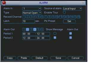 Figure 4-19 4.7 Backup Click backup icon in the main menu, there are two function items: detect device and backup files. 4.7.1 Detect Device Here is for you to view devices information. See Figure 4-20. DETECT DEVICE N Page Up Г Dete 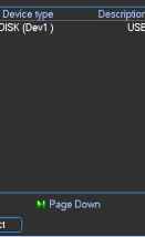 Total capabiliti 1 GL Figure 4-20 4.7.1 Backup Select backup device and then channel, file start time and end time. Click add button, system begins search. All matched files are listed below. System automatically calculates the capacity needed and remained. See Figure 4-21. system only backup files with a V before channel name. You can use Fn or cancel button to delete V after file serial number. Click backup button, you can backup selected files. There is a process bar for you reference. When the system completes backup, you can see a dialogue box prompting successful backup.  Figure 4-21 Click backup button, system begins burning. At the same time, the backup button becomes stop button. You can view the remaining time and process bar at the left bottom. See Figure 4-22. 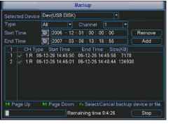 Figure 4-22 Tips: During backup process, you can click ESC to exit current interface; but the system will not terminate backup process. Note: When you click stop button during the burning process, there are two conditions for different devices: For CD/DVD burner device, the stop function becomes activated immediately and there is no data in the burner. For USB device, system can backup the data before you click stop button. For example, if there is a file of 10 minutes, when you click stop after five minutes backup, system only save the previous 5-minute data in the device. The file name format usually is: SN CH+channel number+time Y+M+D+H+M+S. In the file name, the YDM format is the same as you set in general interface. (Main Menu ->Setting ->General).You can visit our website to view listed CD-ROM type. 4.8 PTZ Control and Color Setup Note: All the operation here is based on PELCO protocols. For other protocols, there might be a little difference. 4.8.1 Cable Connection Please follow the procedures below to go on cable connection Connect the dome RS485 port to DVR 485 port.. Connect dome video output cable to DVR video input port. Connect power adapter to the dome. 4.8.2 PTZ Setup Note: The camera video should be in the current screen. Before setup, please check the following connections are right: PTZ and decoder connection is right. Decoder address setup is right. Decoder A (B) line connects with DVR A (B) line. Boot up the DVR, input user name and password. In the main menu, click setting, and then click Pan/Tilt Control button. The interface is shown as in Figure 4-23. Here you can set the following items: Channel: select the current camera channel. Protocol: select corresponding PTZ protocol(such as DH-SD1) Address: default address is 1. Baud rate: select corresponding baud rate. Default value is 9600. Data bits: select corresponding data bits. Default value is 8. Stop bits: select corresponding stop bits. Default value is 1. Parity: there are three options: odd/even/none. Default setup is none. 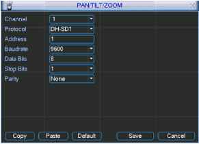 Figure 4-23 After all the setting please click save button. In one window display mode, right click mouse (click Fn Button in the front panel or click Fn key in the remote control). The interface is shown as in Figure 4-24. View 1 View 4 View 9 View 16 WifnIitiiliWHiig Color Setting Search Record Alarm Output Alarm Input Main Menu Figure 4-24 Click Pan/Tilt/Zoom, the interface is shown as below. See Figure 4-25. Here you can set the following items: Step: value ranges fro 1 to 8. Zoom Focus Iris Click icon Ы and У to adjust zoom, focus and iris. PAN/TILT/ZOOM e Zoom 9 e Focus О e Iris (Page Switch) Figure 4-25 In Figure 4-25, please click direction arrows (See Figure 4-26) to adjust PTZ position. There are totally 8 direction arrows.  Figure 4-26 4.8.3 3D Intelligent Positioning Key In the middle of the eight direction arrows, there is a 3D intelligent positioning key. See Figure 4-27. Click this key, system goes back to the single screen mode. Drag the mouse in the screen to adjust section size. It can realize PTZ automatically.  Figure 4-27 Here is a sheet for you reference.
4.9 Preset/ Patrol/Pattern/Scan In Figure 4-25, click the set button. The interface is shown as below. See Figure 4-28. Here you can set the following items: Preset Patrol(Tour) Pattern Border PANmLT/ZOOM xl Function Preset гг П1 Patrol! Patrol Pattern L Border (Tn Patrol No. [o I Set t Del Preset Figure 4-28 In Figure 4-25, click page switch button, the interface is shown as in Figure 4-29. Here you can activate the following functions: Preset Patrol(Tour) Pattern Aux on Aux off Auto scan Auto pan Light on 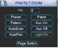 Note: The following setups are usually operated in the Figure 4-25,Figure 4-28 and Figure 4-29 . 4.9.1Preset Setup In Figure 4-25, use eight direction arrows to adjust camera to the proper position. In Figure 4-28, click preset button and input preset number. The interface is shown as in Figure 4-30. Now you can add this preset to one patrol (tour). 1 % PAN/TILT/ZOOM ~ x Function Preset === PatrolNo. [Q Patrol I-1 Pattern (I Set 1 Pattern Border Del Preset Figure 4-30 4.9.2 Activate Preset In Figure 4-29, please input preset number in the No. blank, and click preset button. 4.9.3 Patrol Setup (Tour setup) In Figure 4-28, click patrol button. The interface is shown as in Figure 4-31.Input preset number and add this preset to a patrol (tour). For each patrol (tour), you can input max 80 presets. PAN/TILT/ZOOM Function Preset l Pf .PatrolNo. [г- Patrol I I- Pattern i Add Preset Border (( Del Preset Figure 4-31 4.9.4 Activate Patrol (tour) In Figure 4-28, input patrol (tour) number in the No. blank and click patrol button 4.9.5 Pattern Setup In Figure 4-28, click pattern button and then click begin button. The interface is shown as in Figure 4-32. Then you can go to Figure 4-25 to modify zoom, focus, and iris. Go back to Figure 4-32 and click end button. You can memorize all these operations as pattern 1. PANrriLT/ZOOM Function Pattern l P Patrol No. [гп Patrol L-1 Pattern 1 I Begin Border (l End Figure 4-32 4.9.6 Activate Pattern Function In Figure 4-29, input mode value in the No. blank, and click pattern button. 4.9.7 Auto Scan Setup In Figure 4-28, click border button. The interface is shown as in Figure 4-23. Please go to Figure 4-25, use direction arrows to select camera left limit Then please go to Figure 4-33 and click left limit button Repeat the above procedures to set right limit. 1 pam/tilt/zo6m~ xl Function Pattern l Patrol No. [0 I Patrol - Pattern t Left 1 Figure 4-33 4.9.8 Activate Auto Scan In Figure 4-29, click Auto Scan button, the system begins auto scan. Correspondingly, the auto scan button changes to stop button. Click stop button to terminate scan operation. 4.10 Dome Menu Control In Figure 4-29, click page switch button, the interface is shown as below. See Figure 4-34. Click menu to enter dome menu. The direction arrows here are to control dome menu. Click page switch button, system goes back to Figure 4-25 PANrriLT/ZOOM Xlj 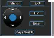 1 2 3 4 5 6 7 ... 12 |
||||||||||||||||||||||||||||||||||||||