
8(903)201-21-74
ООО "ЧетыреДатчика"
|
Оператор: 8(903)201-21-74 ООО "ЧетыреДатчика" |
|
Оператор: 8(903)201-21-74 ООО "ЧетыреДатчика" |
Главная страница Dvr following and features 1 2 3 4 5 6 7 8 ... 12 5 Understanding of Menu Operations and Controls 5.1 Menu Tree This series DVR menu tree is shown as below. 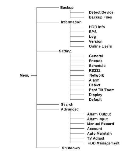 5.2 Main Menu When you login, the system main menu shows as below. See Figure 5-1 . There are totally six icons: search, Information, setting, backup, advanced and shutdown. Move the cursor to highlight the icon, then double click mouse to enter the sub-menu. 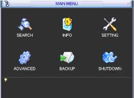 Figure 5-1 5.3 Setting In main menu, highlight setting icon and double click mouse. System setting interface is shown as below. See Figure 5-2. ЩЖ SETTING X I GENERAL ENCODE SCHEDULE RS232 NETWORK С i О ALARM DETECT PANn ILT/ZOOM DISPLAY DEFAULT Figure 5-2 5.3.1 General General setting includes the following items. See Figure 5-3. System time: here is for you to set system time Date format: there are three types: YYYYY-MM-DD: MM-DD-YYYYY or DD-MM- YYYY. Date separator: there are three denotations to separate date: dot, beeline and solidus. Time format: there are two types: 24-hour mode or 12-hour mode. Language: system supports various languages: Chinese (simplified), Chinese (Traditional), English, Italian, Japanese, French, Spanish (All languages listed here are optional. Slight difference maybe found in various series.) HDD full: Here is for you to select working mode when hard disk is full. There are two options: stop recording or rewrite. Pack duration: Here is for you to specify record duration. Default value is 60 minutes. DVR No: when you are using one remote control to control several DVRs, you can give a name to each DVR for your management. Video standard: There are two formats: NTSC and PAL. Auto logout: Here is for you to set auto logout interval once login user remains inactive for a specified time. Value ranges from 0 to 60 minutes. Output mode:there are three options: TV/VGA/AUTO Note: since system time is very important, do not modify time casually unless there is a must. After all the setups please click save button, system goes back to the previous menu. 1 GENERAL xl System Time [2007 - 06 - 07 16 : 16 : 02 Date Format Date Separator Time Format Language HDD Full Pacl< Duration DVR No. Video Standard PAL Auto Logout 10 OutPut Mode [VGA YYYY MM DD 24-HOUR Overwrite Figure 5-3 5.3.2 Encode Encode setting includes the following items. See Figure 5-4. Channel: Select the channel you want. Compression: system supports H.264.Or you can select from the dropdown list. Resolution: System supports various resolutions, you can select from the dropdown list. For this series, we can support CIF. Bit rate: system supports two types: CBR and VBR. Quality: There are six levels ranging from 1 to 6. Level six is the highest image quality. Frame rate: there are six levels: 1 f/s,2f/s,3f/s, 6f/s,12f/s,25f/s. (Some series DVRs only support PAL 25f/s ) Enable audio: you can turn on or off the audio. Cover area (Privacy mask): Here is for you to set window blanking section. You can drag you mouse to set proper section size. Time display: You can select system displays time or not. Channel display: You can select system displays channel number or not. System default setup is: Channel:1 Compression:H.264 Resolution: CIF Bit rate: CBR Quality: 4 Frame rate: 25f/s Please highlight icon = to select the corresponding function. Channel Compression Resolution Bit Rate Quality Frame Rate Overlay Cover-Area Time Display IК 264 I CIF I CBR I25FPS ENCODE Channel Display Default Cancel Figure 5-4 5.3.3 Schedule Please refer to chapter 4.4 schedule. 5.3.4 RS232 RS232 interface is shown as below. Here are five items. See Figure 5-5. Function: There are various devices for you to select. Baud rate: You can select proper baud rate. Data bit: You can select proper data bit. Stop bit: There are three values: 1/1.5/2. Parity: there are three choices: none/odd/even. After all the setups please click save button, system goes back to the previous menu
5.3.5 Network Here is for you to input network information. See Figure 5-6. IP address Subnet mask Gateway Service port: Default value is 37777. (System server port 37778 is reserved for network UDP use.) HTTP port: Default value is 80 Protocol: You can select proper protocol from the dropdown list. Max connection: support maximal 10 users. Properties: There are three options for you: FTP/NTP/Alarm center. You can select corresponding ways and then click properties button to go to setup interface. Authorization: Click authorization button please highlight icon = to enable IP authentication function. When you enable this function, only IP in the list can login this DVR. See Figure 5-7. After all the setups please click save button, system goes back to the previous menu. NETWORK xl IP Address Subnet Mask Gateway Service Port Protocol Enable DDNS. Site Natrie [ 169 . 254 255 . 255 hostname DDNS Server IP Q0 Enable PPPoE (Authorization HTTP Pott [S0 Max ConnectionTo rPropenies I [ГП User Name username Password Default Figure 5-6 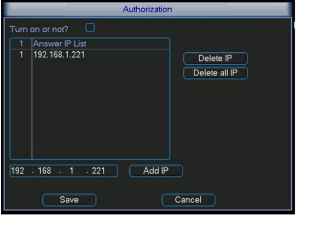 5.3.5.1 PPPoE Connection Enable PPPoE function and then input PPPoE name and PPPoE password you get from your ISP (Internet service provider). Click save button, you need to restart to activate your configuration. After rebooting, IP camera will connect to internet automatically. The IP in the PPPoE is the dynamic value. 5.3.5.2 Web visit via PPPoE There are two ways. a. visit via current IP After DVR connected with Internet by PPPoE, please get your devices current IP in Figure 5-6. Now you can visit this IP camera via this IP. b. Visit via DNS You need a PC of fixed IP in the internet and there is the DDNS software running in this PC. In other words, this PC is a DNS (domain name server). In network DDNS, input your PPPoE name you get from you IPS and server IP (PC with DDNS ) . Click save button and then reboot system. Click save button, system prompts for rebooting to get all setup activated. After rebooting, open IE and input as below: http: (DDNS server IP)/(virtual directory name)/webtest.htm e.g.: http: 10.6.2.85/DVR DDNS/webtest.htm.) Now you can open DDNSServer web search page. 5.3.5.3 FTP You need to download or buy FTP service tool (such as Ser-U FTP SERVER) to establish FTP service. Please install Ser-U FTP SERVER first. From start -> program -> Serv-U FTP Server -> Serv-U Administator. Now you can set user password and FTP folder. Please note you need to grant write right to FTP upload user. See Figure 5-8. 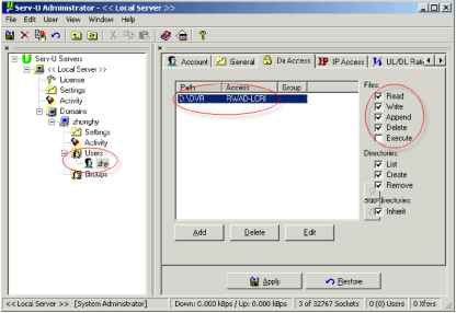 Figure 5-8 You can use a PC or FTP login tool to test setup is right or not. For example, you can login user ZHY to FTP: 10.10.7.7 and then test it can modify or delete folder or not. See Figure 5-9. 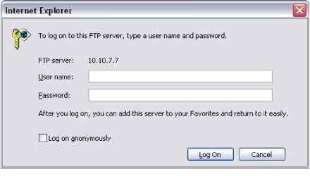 Figure 5-9 System also supports upload multiple DVRs to one FTP server. You can create multiple folders under this FTP. In Figure 5-6, select FTP and then click properties button. You can see the following interface. See Figure 5-10. I FTP SETTING xl enable HOST IP [Ъ DIR NAME \2 USER NAME \2 FILE LENGTH CHANNEL IT PERIOD 1 PERIOD 2 Q0: 00 00: 00 - 00: 00 - 00; 00 ?T 21 PASSWORD 1 INTERVAL fo WEEK fMon MOTION ALARM □ □ □ no □ fOopy Default Cancel Figure 5-10 Please highlight the icon Я jn front of Enable to activate FTP function. Now FTP can upload alarm video and motion detection video. Please note, when you are using this function, please make sure current upload channel is in motion detection or alarm record status and there is video available. Here you can input FTP server address, port and etc. г . IP DIFttJAME pJF~ gSS4 MAMS ;гиг RLELENSm it. CHANNEL ff HTEWW. i 14 WEEK 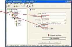 Figure 5-11 File length: upload file length. When setup is larger than the actual file length, system will upload the whole file. When setup here is smaller than the actual file length, system only uploads the set length and auto ignore the left section. Interval: in each channel, system only uploads the first video file in accordance with video type (alarm/motion detection) during the same period. For example, when interval value is 5 minutes, system only uploads the first motion detection or alarm file in each 5-minute. When interval value is 0, system uploads all corresponding files. Period 1 and period 2: you can set two periods for one each channel. System file name is shown as in Figure 5-12. 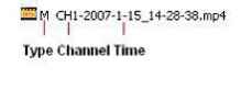 Figure 5-12 5.3.5.4 NTP You need to install SNTP server (Such as Absolute Time Server) in your PC first. In Windows XP OS, you can use command net start w32time to boot up NTP service. In Figure 5-6, select NTP and then click properties button. You can see the following interface. See Figure 5-13. Host IP: Input your PC address. Port: This series DVR supports TCP transmission only. Port default value is 123. Update interval: minimum value is 15(Unit: minute) Time zone: select your corresponding time zone here. Here is a sheet for your time zone setup.
Enable HostIP Port \й TimeZone 0 UpDatelnterval [o Cancel Figure 5-13 5.3.6 Alarm Please refer to chapter 4.6 Alarm Setup and Activation. 5.3.7 Detect Please refer to chapter 4.5 Detect. 5.3.8 Pan/Tilt/Zoom The pan/tilt/zoom setup includes the following items. Please select channel first. See Figure 5-14. Protocol: select corresponding PTZ protocol such as PELCO. Address: input corresponding PTZ address. Baud rate: select baud rate. Data bit: select data bit. Stop bit: select stop bit. Parity: there are three choices: none/odd/even. After all the setups please click save button, system goes back to the previous menu. For detailed setup, please refer to chapter 4.9 preset/patrol/pattern/scan. PANH-ILT/ZOOM Channel 1 Protocol [PELCOD Address l Baudrate [115200 Data Bits [8 Stop Bits [1 Parity [None Default Cancel Figure 5-14 5.3.9 Display Display setup interface is shown as below. See Figure 5-15. Transparency: Here is for you to adjust transparency. The value ranges from 128 to 255. Channel name: Here is for you to modify channel name. Please note all your modification here only applies to DVR local end. You need to open web or client end to refresh channel name. Time display: You can select display time or not. Channel display: You can select channel name or not. Overlay information: System displays some information in the screen for your reference. Enable tour: activate tour function. Interval: Input proper interval value here. The value ranges from 5-200 seconds. In tour process, you can use mouse or click Shift to turn on window switch function. S Stands for opening switch function, Ш stands for closing switch function. View1/4/9/16: System support 1/4/9/16 window tour. Please highlight icon S to select the corresponding function. After all the setups please click save button, system goes back to the previous menu. 1 2 3 4 5 6 7 8 ... 12 |
|||||||||||||||||||||||||||||||||||||||||||||||||||||||||||||||