
8(903)201-21-74
ООО "ЧетыреДатчика"
|
Оператор: 8(903)201-21-74 ООО "ЧетыреДатчика" |
|
Оператор: 8(903)201-21-74 ООО "ЧетыреДатчика" |
Главная страница Dvr following and features 1 ... 3 4 5 6 7 8 9 ... 12 Transparency 200 Time Display 1 Overlay Info Ш Monitor Tour Enable Tour D Channel Name ( Modify Channel Display Ш Figure 5-15 5.3.10 Default Click default icon, system pops up a dialogue box. You can highlight И to restore default factory setup. See Figure 5-16. Select all General Encode Schedule RS232 Network Alarm Detect Pan/tilt/zoom Display Channel name Please highlight icon Я to select the corresponding function. After all the setups please click save button, system goes back to the previous menu. Warning! System menu color, language, time display mode, video format, IP address, user account will not maintain previous setup after default operation! Please select setting entries that you want to restore default SCHEDULE NETWORK PAN/TILT/ZOOM Channel Name Figure 5-16 5.4 Search Please refer to chapter 4.3 Search. 5.5 Advanced Double click advanced icon in the main window, the interface is shown as below. See Figure 5-17. There are totally seven function keys: hard disk management, alarm output, alarm input, manual record, account, auto maintain, and TV adjust.  HDD MANASEMENT ALARM OLTTPUT ALbfiM INPUT MANUAL RECORD ACCOUMT AUTO MAINTAIN Figure 5-17 5.5.1 HDD Management Here is for you to view and implement hard disk management. See Figure 5-18. You can set proper mode for each hard disk from the dropdown list. When you use redundant backup function, you can set one or more redundant HDD(s). Please note you need to set at least one read-write disk, otherwise system will not record video. For detailed information you can refer to chapter 4.4 Schedule. After all the setups please click save button, system needs to reboot to get all the modification activated. HDD MANAGEMENT Щ 2 3 4 О О О О Alarm Set Alarm Release HDD No. Type Read/Write Status Normal Capacity 79.99 GB Record time 00-00-00 00:00:00/00-0 Setto I Read/Write - Read/Write Read only Redundant Format Recover Execute  Figure 5-18 Click alarm set button, the interface is shown as below. See Figure 5-19. Please highlight icon S to select the corresponding function. You can enable one or more alarm setups. The lower limit ranges from 1% to 99%. Alarm channel number ranges from 1 to 6. Delay value is from 0 to 240 seconds. Please note when HDD capacity is not full system only alarms once! After all the setups please click OK button, system goes back to the previous menu I arm Set Alarm When no Disk or Errors Occur Alarm When Free Space is Lower Lower Limit j99 )% Alarm Output 13 Delay 30 Isec. Show Message Ш (i Ш 1 ( Cancel 1 Figure 5-19 5.5.2 Alarm Output Here is for you to set proper alarm output. Please highlight icon S to select the corresponding alarm output. After all the setups please click OK button, system goes back to the previous menu. See Figure 5-20. 10! AUSRM OUTPUT xI 1 2 3 4 5 6 □□□□□□ Figure 5-20 5.5.3 Alarm Input Here is for you to set alarm input. Please highlight icon S to select the corresponding input channel. After all the setups please click save button, system goes back to the previous menu. See Figure 5-21. \<Ш ALARM INPUT xl 1 2 3 4 5 6 7 9 10 11 12 13 14 15 16  Figure 5-21 5.5.4 Manual Record Please refer to chapter 4.2.2 manual record. 5.5.5 Account Here is for you to implement account management. See Figure 5-22. Here you can: Add new user Modify user Add group Modify group Modify password. For account management please note: System account adopts two-level management: group and user. No limit to group or user amount. For group or user management, there are two levels: admin and user. The user name and group name can consist of eight bytes. One name can only be used once. There are four default users: admin/888888/666666 and hidden user default . Except user 6666, other users have administrator right. Hidden user default is for system interior use only and can not be deleted. When there is no login user, hidden user default automatically login. You can set some rights such as monitor for this user so that you can view some channel view without login. One user should belong to one group. User right can not exceed group right. About reusable function: this function allows multiple users use the same account to login. After all the setups please click save button, system goes back to the previous menu. 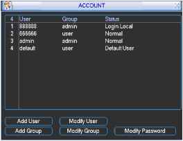 Figure 5-22 5.5.6 Auto Maintain Here you can set auto-reboot time and auto-delete old files setup. See Figure 5-23. You can select proper setup from dropdown list. After all the setups please click save button, system goes back to the previous menu. AUTO MAINTAJN Auto-Reboot System Every Monda> - at 00:00 Auto-Delete Old Files. 30 Days ago h-  Figure 5-23 5.5.7 TV Adjust Here is for you to adjust TV output setup. See Figure 5-24. Please drag slide bar to adjust each item. After all the setups please click OK button, system goes back to the previous menu. TV ADJUST Top Deflate Bottom Deflate Left Deflate Rigtit Deflate Brigfitness Figure 5-24 5.5.8 Video Matrix (For DVR 1604LNH-S Series Only) Some series DVR have the matrix and loop outputs. 5.5.8.1 Loop outputs They are just the same with video distributors. There are 16-ch video loop outputs from our DVR. The DVR video output can connect with other devices such as TV walls, analog matrix and so on. 5.5.8.2 Matrix outputs They are like the small-scale matrix. You can select any camera from our DVR to switch. And the output can also tour between the cameras. So the matrix outputs can be used to build TV walls and tour and display the cameras one by one. 5.5.8.3 Rear Panel Connection The rear panel is shown as below. See Figure 5-25. Connect to 37-pin Cable  Ф Ф Ф Ф Ф ® <*vvc* LJ Figure 5-25 5.5.8.4 37-pin cable introduction There are three colors cable. See Figure 5-26. Black: for loop outputs, there are 16-ch loop outputs Blue: for matrix outputs, there are 4-ch matrix outputs White: for bi-direction talk, one is for audio in and the other is for audio out. Figure 5-26 5.5.8.5 Matrix setup 5.5.8.5.1 Enter the Menu of Video Matrix In the menu, from Advanced to Video Matrix . See Figure 5-27. is ADVANCED Xl HDD MANAGEMENT ALARM OUTPUT ALARM INPUT MANUAL RECORD ACCOUNT AUTO MAINTAIN TV ADJUST VIDEO MATRIX Figure 5-27 5.5.8.5.2 Right mouse menu In one-window display mode, right click mouse to select Video Matrix . See Figure 5-28. РапГП It/Zoom Color Setting Alarm Output Alarm Input VideOjMatrix Main Menu Figure 5-28 5.5.8.6 Video Matrix Interface and Application LNH-S series support 1-channel matrix outputs. The video matrix interface is shown as in Figure 5-29. You can set for each channel. The function consists of two types. ijl? VIDEO MATRIX X I Video Output 1 Group 1 I All Group 2 1 Group 3 3 Group 4 -- Group 5 -- Group 6 1 Enable Tour Ш Alarm In P Figure 5-29 5.5.8.6.1 Single Tour Please enable tour function. Then set interval time and select corresponding cameras. You can select ALL to tour between all channels. Note: - - means that there is no alarm activation tour. 5.5.8.6.2 Alarm Tour Select the alarm in channel number from the dropdown list. If there is an alarm signal from the channel selected, the matrix output will go to tour as you set in the Alarm setting (Main Menu->Setting->Alarm). See Figure 5-30. Alarm tour has higher priority than single tour during this period, the single tour will stop. After alarm activation tour, the matrix output will continue single tour. Alarm In 1 - Source of alarm [Local Inpul I Type NormalOpen Enable Tour □ Record Channel в g0 . il] Sill [E И (HI 111 3103 (III 21 Delay 110 ]sec. Piz Preset [ get ) Alarm Out HLtjSLillAKl] Alarm Out Show Message Figure 5-30 5.5.8.7 Examples 5.5.8.7.1 Example one In Figure 5-31, matrix outputs 1 , 3 , 4 tour between all cameras of the DVR. Matrix output 2 tours between CAM1, CAM6 and CAM7 of the DVR. The interval is five seconds. VIDEO MATRIX Video Output Group 1 Group 2 Group 3 Group 4 Group 5 Group 6 Enable Tour Alarm In Figure 5-31 5.5.8.7.2 Example two In Figure 5-32, when alarm occurs in channel one, the activated matrix output one begins touring between CAM1, CAM3 and CAM4 of the DVR until alarm activation tour stops. Alarm In 1 [-l Source of alarm [Local Input Type Normal Open -J Enable Tour Q Record Channel Ц (1)(Т|(](Т|(10(П1(Ш1(й|111111 Delay [10 I sec. Ptz Preset Set ) Alarm Out [Т|[2][з](Т|[Г|[б) Alarm Out Show Message Period 1 [00: 00 24: 00 Period 2 loo: 00 - 24: 00 Copy ] I Paste ] f Default Save Cancel Figure 5-32 5.6 Information Here is for you to view system information. There are totally five items: HDD (hard disk information), BPS (data stream statistics), Log and version, and online user. See Figure 5-33. 11 INFO Xl 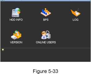 5.6.1 HDD Information Here is to list hard disk type, total space, free space, video start time and status. See Figure 5-34. Note: Please remove the broken hard disk before you add a new one. Once there is a hard disk confliction, please check hard disk time and system time is the same or not. Please go to setting then general to modify system time. At last, reboot the system to solve this problem. If disk is damaged, system shows as ? SATA 12 3 4 О О О 0 Read/Write Read/Write Read/Write Read/Write Total Space 319.98 GB 79.99 GB 79.99 GB 79.99 GB 79.99 GB Free Space 319.97 GB 79.99 GB 79.99 GB 79.99 GB 79.99 GB Normal Normal Normal Normal H Page Up \4 Page Dowri Figure 5-34 5.6.2 BPS Here is for you to view current video data stream (KB/s) and occupied hard disk storage (MB/h). See Figure 5-35.  Figure 5-35 5.6.3 Log Here is for you to view system log file. System lists the following information. See Figure 5-36. 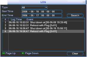 5.6.4 Version 1 ... 3 4 5 6 7 8 9 ... 12 |