
8(903)201-21-74
ООО "ЧетыреДатчика"
|
Оператор: 8(903)201-21-74 ООО "ЧетыреДатчика" |
|
Оператор: 8(903)201-21-74 ООО "ЧетыреДатчика" |
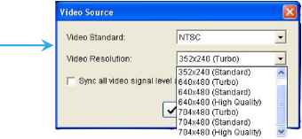
Главная страница Nvr/dvr/hybrid ndvr 1 ... 6 7 8 9 10 11 12 ... 14 Black / White List 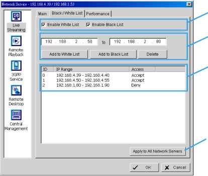 Enable list IP address Black/ White list Apply to all White List: Check the Enable White List box to activate the white list filter. Only IP from the white list is allowed to log in. Black List: Check the Enable Black List box to activate the black list filter. IP from the black list will be blocked. IP Address: Enter an IP address into the IP address field on the left. To add an IP address range to the system, enter 2 sets of IP address to indicate a series of IP(s). Add/Delete: Add the IP(s) onto the list or remove it from the list. Apply to All Network Servers: Apply the settings to both the live streaming server and the remote playback server. Options: Adjust the setting only when the server is stopped. Port: Assign a port for the clients to connect to your system via Remote Live Viewer. Default port is 5150. Maximum Connections: Number of connections that are allowed to connect to the system. Default is 16 channels and maximum is 128, one camera video counts as one connection. Use Default Web Server: Activate the Web server by checking the box; clients will be able to watch live video via Internet Explorer. The port for live streaming server is set to 80 by default. Note: This must be checked in order to access system via IE*. Save Log: Save the log information at appointed folder. Enable Audio: Select this option to enable the audio transmission along with video stream. Performance Total bit rate \ Individual Camera bit rate information / 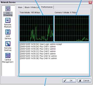 Live Streaming Server log info rmation 5.17.2 Remote Playback S erver When starting the remote playback function, the system allows remote users to log in to the specific computer and withdraw data files that are stored on it. As system administrator, user could be able to monitor the accounts logging in to maintain the system efficiency. Main On Remote Playback Server panel, administrator can see all the clients who are currently logging in to the computer and watching the playback video from the remote side. 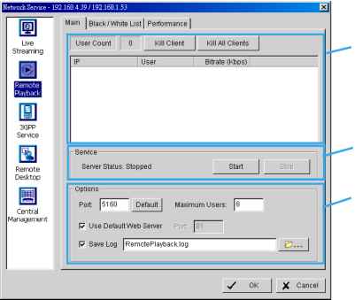 . Client list Service Options Black / White List and [Performance! - Please refer to Live Streaming Server section Client list: User Count: Show the number of users that are connecting to system. Kill Client: Highlight an IP address and click on the Kill Client button to block the client from your client list. Kill All Clients: Click on this button and then block all the clients logging to your system. Service: Server Status: Click on Start/Stop to turn on/off this option. Options: Adjust the setting only when the server is stopped. Port: Assign a port for the clients to connect to your system via Remote playback server. Default port is 5160. Maximum Users: Number of connections that are allowed to connect to the system. Default is 8 users and maximum is 64. Note: One user counts as one account that is logging in to the server. Use Default Web Server: Activate the Web server by checking the box; clients will be able to watch live video via Internet Explorer. The port for live streaming server is set to 80 by default. Note: Must check this item for system access via IE*. Save Log: Save the log information at appointed folder. 5.17.3 3GPP Service When starting the 3GPP service function of your computer, the system allows remote users to log in and view cameras that are connecting to it with 3GPP supported mobile phone. See Appendix A for more details about 3GPP Service. EZll и Live Streaming Remote Playback Client Count 0 State IP I Camera Uger Agent Remote Desktop Central Management Client list Seг^er Status: Stopped Stop nOptic Port: 554 Default Enable UserAuthentication У OK \ X Cancel Service -Options Client list: Client Count: Show the number of channels that are connected to system. Service: Server Status: Click on Start/Stop to turn on/off this option. Options: Adjust the setting only when the server is stopped. Port: Assign a port for the clients to connect to your system via 3GPP Service. Default port is 554. Enable User Authentication: User need to insert the username and password to login to the 3GPP server and view the video stream. 5.17.4 Remote Desktop When starting the Remote Desktop, the system allows remote users to use NUUO Remote Desktop Tool to login and configure system. See Appendix B to install and use this tool. 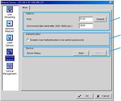 Option Authentication Server Status Options: Port: Assign a port for NUUO Desktop tool to login and configure system. Disconnect idle client after (300~3600 sec): Auto disconnect the on-line user who idled more than set period. Authentication: Enabling this option would only allow admin account to use NUUO Desktop tool to login system. Service: Server Status: Click on Start/Stop to turn on/off this option. 5.17.5 Central Management Service * Note: This function is not available under NUUO NVR Lite license. This service only supports NUUO Central Management System (NCS). Having started the Central Management Service, Main Console sends event information to NCS and allows the NCS system to control I/O devices from a remote site. Note: 1. To enable this action, go Guard >Action and select Send to Central Server to enable the action triggered by preference event. 2. Please refer to the user manual of NUUOs Central Management System for detailed information. Network Service - 0.0.0.0 / 192.16B.0.B3 / 21 B.I 67.191.175 Live Streaming Remote Playbad! Ш 3GPP Service Ш Remote Desktop Central iManagement Kill Client Kill All Clients Server Status: Stopped r Options- Port: 5170 I Default Maximun Connections: [Тб~ (7QK stop X Cancel Client Service Options Client list: Client Count: Show the amount of NCS Servers that are connected to system. Kill Client: Highlight an IP address and click on the Kill Client button to block the client from your client list. Kill All Clients: Click on this button and then block all the clients logged in to your system. Service: Server Status: Click on Start/Stop to turn on/off this option. Options: Adjust the setting only when the server is stopped. Port: Assign a port for NCS System to connect Main Console system. Default port is 5170. Number of connections from NCS Servers that are allowed to connect to the system. The default is 8 NCS Servers and maximum is 16. 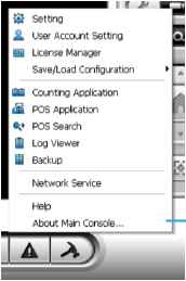 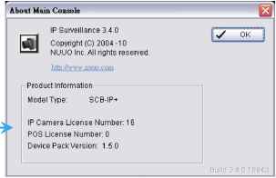 5.20 Video Source Note: Not supported under Lite license Step 1: Go to Video Source to adjust the Video Standard to NTSC or PAL. Step 2: Adjust the maximum Video Resolution for all analog cameras.(MPEG4 only)
Step 3: For MPEG4, click Sync all video signal level after pressing OK to synchronize video signal level to the optimized display (Auto-gain control). For HD, click Sync all video signal level to auto detect video resolution (1080P/720P)
 5.18 Help Click Help to connect to FAQ of NUUO website http: support.nuuo.com/mediawiki/index.php/Main Page . 5.19 About Main Console Go to About Main Console for detailed system and license information. 6, E-Map 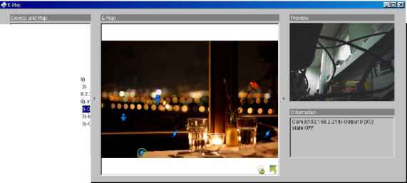 0 Н Map Q- Airport i-Я East Oate Я Bistro B- Device Cam1 4 Cam3(192.1 Cam4 (192,1 AXIS Q1755 (192.1 > Cam3(1 92.1 68,2.21 Cam4 (192 1 68.2.21 4 Cam4 (192 1 68.2.21  2.21 2.21 J With E-Map, users can easily track the actual location of an occurring event, at the moment it happens. The arrow and lightning icons on E-Map represent cameras and I/O devices. These icons will turn red once they are triggered by alarms. To launch the E-Map application, simply click on Start and select Open E-Map from the start menu for the E-Map window. There are 2 modes available in the E-Map application: Edit mode: Allows users to add/edit maps and indicators of devices. In Edit mode, the function buttons on the bottom of the window will be available. Please complete configurations before running E-map function for the first time. Л Operate mode: All settings will be activated in this mode. 6.1 Edit Mode All E-map modifications must be configured in Edit Mode. 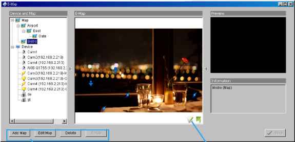 Function button Edi* m°de/ Operate mode Switch button 6.1.1 Add/Edit/Delete Map Add E-Map: Step 1: Click on the switch button to switch to Edit mode. Make sure all devices are connected and setup properly. Step 2: Right click on the Map icon in device and map list to obtain the option menu to add map, or just click Add Map button to obtain the Map Config dialog. I M<ip Config Map Image File: P Map Name: P Step 3: Select the map file and insert the map name. Click OK, and then the map you added appears in the tree structure of device and map list. Step 4: The map indicator appears on the left-up corner of parent map. Drag it to the position you want on appointed map. Edit E-Map: Step 1: Make sure you are in Edit mode and all devices are connected and inserted. Step 2: Right click on the Map icon to obtain the option menu to edit map, or just click the Edit Map button to obtain the Map Config dialog. Step 3: Modify the required details, and then click OK to save configuration. Delete E-Map: Step 1: Make sure you are in Edit mode and all devices are connected and inserted. Step 2: Right click on the Map icon to obtain the option menu to delete map, or just click the Delete button to remove appointed map from list. Note: The root map cannot be deleted. 6.1.2 Add/Rotate/Delete Device Indicator Add Indicator: Step 1: Make sure you are in Edit mode and all devices are connected and inserted. Step 2: Click on the Map icon to go to the desired map layer. Step 3: Please make sure the map you want is displayed. Select device from the list and drag a device directly to the desired location on the map. Note: Different devices are symbolized by different indicators. Camera indicator, Ж-Digital Input indicator, -- Access Control indicator, -POS indicator, Digital Output indicator - LPR indicator Rotate Indicator: Step 1: Click on an existing camera indicator on your map under Edit mode. This camera indicator will be marked with a green ring . Step 2: Each click on the Rotate button rotates the indicator 45 degrees clockwise. Note: Only camera indicators are allowed to be rotated. Delete Indicator: Step 1: Click on an existing camera indicator on your map under Edit mode. This camera indicator will be marked with a green ring . Step 2: Click on the Delete button and the indicator will be gone. 6.2 Operate Mode After configuration under Edit mode, switch to Operate mode to commit settings. 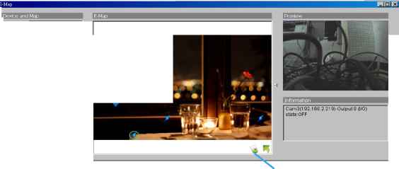 Map B- Airport i @ East :...e Gate Bistro g... Device I.....Cami \ 4 Cam3(1 92.1 68.2.21 9) I.....Cam4 (192 168 2 21 3) i AXIS Q1 755 (1 92.168,2.: i.....l/ CamSd 92.1 68.2.21 9)-lr Cam4 (192 16 Cam4 (192 16 1 de ! at 1,2.213)-! I I 2.213)-(l ..... ite. Operate mode/ Edit mode Switch button 6.2.1 Device and Map Tree list This window will list all devices and map hierarchies; click device or map indicator to show related information on E-Map windows. Map - Select the map you want to show on E-Map Window. Camera - A preview of the selected camera will show in the preview window. The indicator, if previously created, will be highlighted on the map. Digital Input/Output - Select to highlight the device with a green ring on the map and show status on Information window. If the Digital Input/Output is from an IP camera, the preview window will display live video of the camera. Ш *Й Access Control/POS/LPR - Select to highlight the Access Control / POS / LPR device with a green ring on the map, and display live video of the first associated camera on the preview window. 6.2.2 E-Map picture This window will show the map layer and indicators. Device Indicator: Select device indicators from the Device and Map Tree list for related information and to preview video. Map indicator: Selecting a map indicator will bring you to that map layer. To return to an upper layer, right click on the map and select UP or click on the map layer. 6.2.3 Information and Preview windows This window will show the related information of each indicator. S Map Info - Shows map name. Camera - Shows camera name and connection status. Digital Input/Output - Shows Digital Input / Output name and status (0 or 1). Й 6Й Access Control/POS/LPR - Shows metadata device name, connection status, first associated camera name and connection status. 6.3 Layout Adjustment Triangular indicator 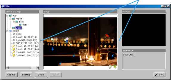 Shrink the window: Click on <l Triangular indicators to hide the Device and Map or Preview and Information windows on the right and left sides. Click again to go back to the default layout. Full screen display: For systems with dual monitor, users can view Main Console on the primary monitor, and view a full-sized E-Map on the secondary monitor. Step 1: Click on l> <l Triangular indicators to hide the Device and Map or Preview and Information windows on the right and left sides. Step 2: Click on the upper-right corner of the window for the full screen mode of E-Map. 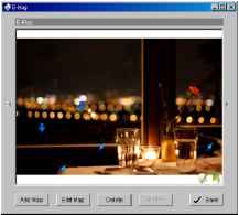 1 ... 6 7 8 9 10 11 12 ... 14 |
|||||||||||||||||||||||||||||||||||||