
8(903)201-21-74
ООО "ЧетыреДатчика"
|
Оператор: 8(903)201-21-74 ООО "ЧетыреДатчика" |
|
Оператор: 8(903)201-21-74 ООО "ЧетыреДатчика" |
Главная страница Nvrmini 2 user manual 1 ... 8 9 10 11 12 13 14 ... 16 in video display while increasing the CPU loading. 6. Select monitor(s) to run LiveView. 7. Click the OK button. 5.2.4 Camera Group Setting You can put different cameras into the same group. 1. Startup > NUUO NVRmini 2 > Remote Live Viewer. 2. Click the General Setting button. 3. Click the Group tab. 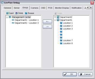 4. Log in to all the servers that contain the camera(s) you would like to put into the group(s). 5. Click the Insert button to create a new group. 6. Name this group. 7. Highlight the camera(s) that you would like to add into this group and then click the <-- button. 8. Repeat step 6 to establish the group. 9. Repeat steps 3 through 7 to establish other groups. 10. Click the OK button. 5.2.5 Delete/ Rename Camera Groups 1. Startup > NUUO NVRmini 2 > Remote Live Viewer. 2. Click the General Setting button. 3. Click the Group tab. 4. Click the group which you want to modify. 5. Click the Delete or Rename button to remove or rename that group. 6. Repeat steps 3 and 4 to modify other groups. 7. Click the OK button. 5.2.6 Stream Profile Setting Select the preferred stream type of each camera as default live view profile. 1. Startup > NUUO NVRmini 2 > Remote Live Viewer. 2. Click the General Setting button. 3. Click the Camera tab. 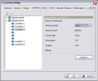 4. Adjust the stream profile of every camera with stream profile enabled in the setting page. 5. Click a camera and select its stream profile, and click the Copy to button to apply this profile to other channels. 6. Click the OK button. 5.2.7 OSD (On-screen display) Setting 1. Startup > NUUO NVRmini 2 > Remote Live Viewer. 2. Click the General Setting button. 3. Click the OSD tab. 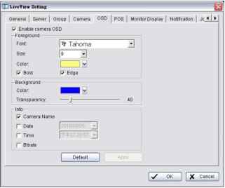 4. Check the Enable camera OSD option. 5. Set the foreground and background settings of the OSD. 6. Select which kinds of information will be displayed on the screen. 7. Click the Apply button to preview the result. 8. Click the Default button to back to the default settings if necessary. 9. Click the OK button. 5.2.8 Monitor Display Setting 1. Startup > NUUO NVRmini 2 > Remote Live Viewer. 2. Click the General Setting button. 3. Click the Monitor Display tab. (И LiveTiew Setting General I Sen/er I Group I Camera I OSD I POS Monitor Display Notification I JcJJ± Monitor #1 Resolution 1280x800 Auto scan Auto scan group: Primar/channel: Secondary channel: Auto scan inteival: I (Not Used) 3 I (Not Used) 3 Auto Scan 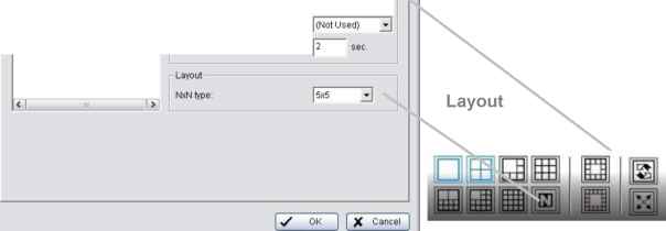 4. Select appointed server group to activate auto scan. 5. Select Primary channel which will always be on the screen when activating auto scan; while select Secondary channel which has second priority when activating auto scan. Enter the time interval for auto scan. 6. Select the screen division of NxN type. 7. Click the OK button. 5.2.9 Notification 1. Startup > NUUO NVRmini 2 > Remote Live Viewer. 2. Click the General Setting button. 3. Click the Notification tab. 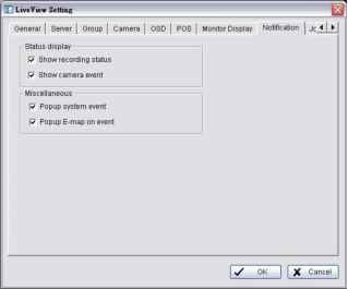 4. Check Show recording status to show the crystal ball with recording status on monitor display. 5. Check Show camera event to display the words of detected camera event on the correspondent screen. 6. Check Popup system event to pop up system event message dialog as a warning when a system event occurred. 7. Check Popup E-map on event to pop up E-map with event indicator when camera or I/O Box event occurred 8. Click the OK button. Popup E-map on event only activates on event, which means that you should not only edit camera and I/O on E-map but setup camera motion, camera input and I/O Box input as an event. Refer to Event & Action Management to do the settings.  5.2.10 Set up Joystick Control 1. Startup > NUUO NVRmini 2 > Remote Live Viewer. 2. Click the General Setting button. 3. Click the Joystick tab. 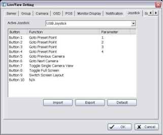 Function: You can choose the function from the drop-down menu for the button of the joystick. 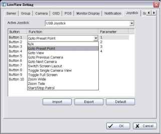 Parameter: Choose the preset point from the drop-down menu. Default: Click to back to default setting. Import: Click to import the settings. Export: Click to export the settings. 11 2 4. Click the OK button. 5.2.11 Set up Live View Sound on Event 1. Startup > NUUO NVRmini 2 > Remote Live Viewer. 2. Click the General Setting button. 3. Click the Sound tab. 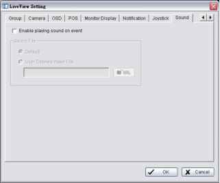 4. Check the Enable playing sound on event option. 5. Select sound file, default sound or user defined sound (.wav). 6. Click the OK button. The function only activates on event, which means you have to setup camera motion, camera I/O and I/O Box I/O as an event. Refer to Event & Action Management to do the setting. 5.2.12 Set up Remote Live Viewer 1. Startup > NUUO NVRmini 2 > Remote Live Viewer. 2. Click the unit you wish to access in your remote server list. 3. Click the LOG IN button to access your unit. 4. Select a camera(s) from the camera list on the right and then drag it to where you wish the image to be displayed.  6. E-Map There are two ways to execute the live view function: by Internet Explorer or by Remote Live Viewer application. With E-map, user can easily track the device location and alarm status with instant response when an event occurs. The arrows and lightening icon on E-map represent cameras and I/O devices. These icons will turn red as being triggered by alarms. There are two modes in E-map application, Edit Mode and Browse Mode. 9f Edit Mode: The function buttons on the bottom of this E-map dialog will be active. Users can add/edit/delete maps and indicators of devices. % Browse Mode: Users are not allowed to do any configuration but check the map hierarchies and device list to see indicators and related information. 6.1 Internet Explorer 1. Open Internet Explorer and log in to the unit. 2. Click the Live View button on the top of the page. 3. Click the Start Menu button and select Open E-Map. 6.1.1 E-Map Control Panel 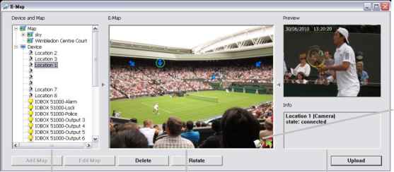 Device and Map Tree List E-Map Picture Edit Mode / Browse Mode Switch Button Preview Window and Information Map: Select a map you want to show on E-map Window. Camera: Select the camera to see preview video or mark indicator on E-map. Digital Input: Select it to highlight the device with green ring on map and show status on Information Window. If the Digital Input is from IP camera, the preview window will display live video of the camera. Digital Output: Select it to highlight the device with green ring on map and show status on Information Window. If the Digital Output is from IP camera, the preview window will display live video of the camera. Ш Map Indicator: Clicking the indicator will lead to the next map layer. If you want to move to the upper layer, select it by mouse directly or click icon on the map. ♦ Camera Indicator: The indicator of cameras dragged from Device and Map Tree List to show preview video and related information. When event occurs, the color of indicator will turn red. X Digital I/O Indicator: The indicator of I/O devices dragged from Device and Map Tree List to show related information. When event occurs, the color of indicator will turn red. Information Window: The window shows the related information of each indicator. > Map: Show map name. > Camera: Show camera name and connecting status. > Digital Input: Show Digital Input name and status (0 or 1). > Digital Output: Show Digital Output name and status (0 or 1). 6.1.2 Add Map 1. Make sure being in Edit Mode and all devices are inserted and connected. 2. Right click on the Map icon Ш in Device and Map Tree List to obtain the option menu to add map, or just click the Add Map button to configure. 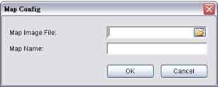 3. Select a map file and insert a name. Click the OK button, and then the map you added appears in the Device and Map Tree List. 4. The map indicator IS appears on the upper left of map. Drag it to the position you want on appointed map. 11 5 5. Repeat steps 2 through 4 to add more maps. 6. Click the Upload button to activate all the settings. The maximum file size of each map is 500KB. There are 10 layers of map, and the map capacity of each layer is 10. 6.1.3 Edit Map 1. Make sure being in Edit Mode and all devices are inserted and connected. 2. Right click on the Map icon in Device and Map Tree List to obtain the option menu to edit map, or just click the Edit Map button to configure. 3. Repeat step 2 to edit more maps. 4. Click the Upload button to activate all the settings. 6.1.4 Delete Map 1. Make sure being in Edit Mode and all devices are inserted and connected. 2. Right click on the Map icon in Device and Map Tree List to obtain the option menu to delete map, or just click the Delete button. 3. Repeat step 2 to delete more map. 4. Click the Upload button to activate all the settings. 6.1.5 Add/Rotate Device Indicator 1. Make sure being in Edit Mode and all devices are inserted and connected. 2. Select the map which you want to add device indicator on. 3. Select a device from list and directly drag it to the desired location on the map. 4. Select a camera indicator and right click on the indicator or click the Rotate button to adjust the direction of camera indicator if needed. 5. Repeat steps 2 and 4 to add more indicators on. 6. Click the Upload button to activate all the settings. 6.1.6 Delete Device Indicator 1. Make sure being in Edit Mode and all devices are inserted and connected. 2. Select the indicator and right click on the indicator or click the Delete button. 3. Repeat step 2 to delete more indicators. 4. Click the Upload button to activate all the settings. 11 6  6.1.7 Layout Adjustment Adjust the Layout 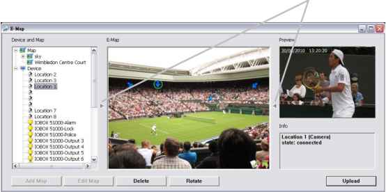 t> Adjust the Layout: Click the triangular indicator to hide the Device and Map Tree List / Preview and Information Window on right and left side of the window. Click the indicator again to back to the default. Ш Maximize the Map: Click the icon on the upper right to get the full screen display of E-map. 6.1.8 Relative Configuration and Application When an event occurs, related E-map pops up to indicate the location of this event. Please check the Notification function for details. 1 ... 8 9 10 11 12 13 14 ... 16 |