
8(903)201-21-74
ООО "ЧетыреДатчика"
|
Оператор: 8(903)201-21-74 ООО "ЧетыреДатчика" |
|
Оператор: 8(903)201-21-74 ООО "ЧетыреДатчика" |
Главная страница Nvrmini 2 user manual 1 ... 3 4 5 6 7 8 9 ... 16 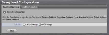 4. Check the box of E-Map Settings or POS Settings if you want to keep the configuration. 5. Click the OK button. 6. The configuration file will be generated into the chosen folder. 2.6.10 Load Unit Configuration / Default Settings Load configuration can let you apply another units settings to the current unit; Load Default Settings will revert all of the units settings back to the default factory settings. 1. Click Management / Save / Load Configuration. 2. Click the Load Configuration tab. 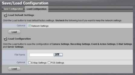 3. Follow the direction to Load Default Settings or Load Configuration. For the former, uncheck the box of Network Settings to keep the IP address; for the latter, check the box of E-Map Settings or POS Settings if you want to restore the configuration. 4. Click the Load button. 5. A confirmation dialog pops up. Click the OK button to begin to load the settings into your unit. If there is POS database existed in the unit, loading configuration with different POS application config is likely to make the original POS data unsearchable. If the saved configuration is without E-map or POS settings, selecting loading configuration with E-map/POS settings will lead you get the default. The original E-map/POS settings (if any) are covered and untraceable. User account and privilege will be kept even if loading default settings, while camera settings, recording schedule, event & action settings, E-mail setting and server settings wont be. RAID information will always be kept whether loading default settings or loading configuration. 2.7 System 2.7.1 View System Information 1. Open Internet Explorer and log in to the unit. 2. Click System / System Information. 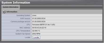 The system information includes the following items. Operating System: Embedded Linux NVR Version: NVR system version Camera package version: Camera package version CPU: CPU model number MAC Address: MAC address of this unit CPU Temperature System Fan Speed Locate: Click to trigger the buzzer to let you know where the unit is    2.7.2 Smart Fan Control 1. Open Internet Explorer and log in to the unit. 2. Click System / System Settings. 3. Click the Fan Control tab. 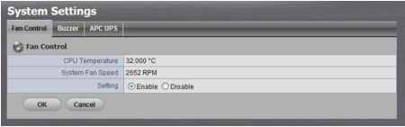 4. Check the Enable or Disable option. 5. Click the OK button. 2.7.3 Buzzer Configuration There is a buzzer in the unit. When the unit finishes booting or when a problem is detected, this buzzer will sound. This buzzer is enabled by default. You can disable/enable this buzzer with the following steps. (We recommend that this buzzer should be enabled.) 1. Open Internet Explorer and log in to the unit. 2. Click System / Settings. 3. Click the Buzzer tab. 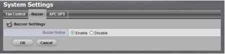 4. Check the Enable or Disable option. 5. Click the OK button. 2.7.4 UPS Setup This feature enables you to tell your unit how long to run on APC Uninterruptable Power Supply (UPS) battery power and when to shutdown, after power failure. 1. Attach the APC UPS to one of the units USB ports. 2. Open Internet Explorer and log in to the unit. 3. Click System / Settings. 4. Click the APU UPS tab. 5. Check one of the options: 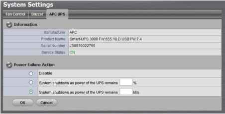 Disable: Run until the UPS battery is depleted System shutdown as power of the UPS remains %: Run until the UPS battery remains this percentage. System shutdown as power of the UPS remains min.: Run until the UPS battery remains the certain period of time. 6. Fill in the specific value if you choose the last two options. 7. Click the OK button. 2.7.5 Upgrade the System 1. Open Internet Explorer and log in to the unit. 2. Click System / Upgrade. 3. Click the Firmware Upgrade tab. 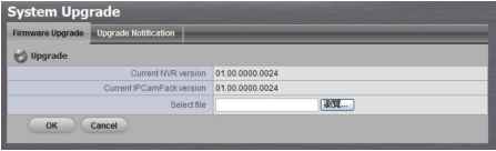 4. Browse the FW for upgrading and click the OK button. 5. A confirmation dialog pops up. Click the OK button to start upgrade process. 6. After upgrade, the system will restart. You need to re-access the unit again after this. 2.7.6 Upgrade Notification Enable this function to allow us to notify you automatically when there are firmware updates (Recommended). This will help keep your system up to date. The updater will also collect info from your system that will be used for future system improvements. 1. Open Internet Explorer and log in to the unit. 2. Click System / Upgrade. 3. Click the Upgrade Notification tab. 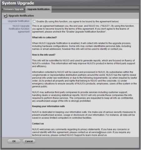 4. Check the option if you agree to be bound by the agreement. 5. Click the OK button. 2.7.7 System Date and Time Setup 1. Open Internet Explorer and log in to the unit. 2. Click System / Date/Time. 3. Click the Setup tab. 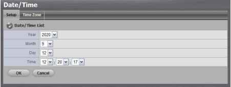 4. Choose the year, month, day and time. 5. Click the OK button to restart the system to activate the changes. When you modify the date or time of the system, the system may find the wrong data when searching the recorded data. Backup the recorded data before changing the time. 2.7.8 Daylight Saving Time Setup 1. Open Internet Explorer and log in to the unit. 2. Click System / Date/Time. 3. Click the Time Zone tab. 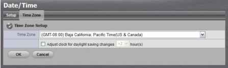 4. Check the Adjust clock for daylight saving changes option and select the time change of daylight saving time in your location. 5. Click the OK button. 2.7.9 Restart the Unit 1. Open Internet Explorer and log in to the unit. 2. Click System / Reboot/Shutdown. 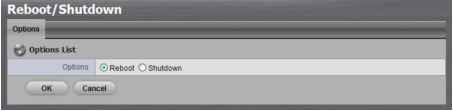 3. Check the Reboot option. 4. Click the OK button. 5. A confirmation dialog pops up. Click the OK button to reboot the unit. The restart procedure runs automatically. When the unit is fully online: The System Status LED turns blue. The buzzer beeps one time (if the buzzer is enabled).  During system restart, none of your files will be accessible from your desktops/laptops. 2.7.10 Shut Down the Unit The only time you need to shut down the unit is to replace the disk drive cooling fan or the power supply. During and after the shutdown, none of your files will be accessible from your desktops/laptops. There are two ways to shutdown the unit. Shutdown by Software 1. Open Internet Explorer and log in to the unit. 2. Click System / Reboot / Shutdown. 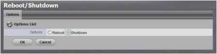 3. Check the Shutdown option. 4. Click the OK button. 5. A confirmation dialog pops up. Click the OK button to shutdown the unit. Direct Shutdown 1. Open the lid of the unit. 2. Press and hold the power button for 2 seconds and release your hands when the buzzer is beeping once. 3. System will begin the shutdown process, which takes about 30 seconds to few minutes depends on number of recording channels and other factors. If the system is crashed and stocked, you can press the power button and hold it for 10 seconds to force to cut off the power directly. We dont recommend to do it if the system work properly.   3. POS 3.1 Introduction 3.1.1 System Introduction NUUO POS, a Point of Sales Systems based on NUUO NVR/DVR/NVDR/NVRmini/NVRmini 2, provides financial transactions surveillance solution in one central system. The architecture is as below; POS transaction data flows to NVRmini/NVRmini 2 by Ethernet. Each Cash Register with an external receipt printer is connected by DB9 cable. The transaction information delivered in R232 format can be converted to Ethernet through SCB-C31A POS data capture converter. 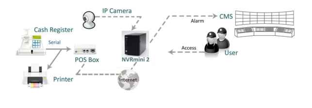 Definition of Terms
Product Specification
Operating Humidity 0-90 % Non-Condensing
3.1.2 Hardware Installation - SCB-C31A To connect Cash Register, Printer, and SCB-C31A POS data capture converter together, please follow below steps: Step 1: Please refer the user manual to setup Cash Register and printer. Step 2: Using a Y-shape DB-9 cable, one DB-9 female connect to POS system and one DB-9 male connect to the receipt printer Y-shape (provided by Printer vendor). Step 3: Using another DB-9 female connect to SCB-C31A POS Data Capture R232/Ethernet converter with Null modem. There are two kinds of serial cable: Straight pass-through and Null-Modem. The connection between SCB-C31 POS Data capture box and Y-cable must be null modem (in package). Step 4: Check the system switch of the SCB-C31A is switched to OFF-OFF position. Step 5: Connect SCB-C31A with power source. Step 6: Connect SCB-C31A with internet port by RJ45 LAN cable. Cash reqister  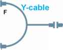 M F SCB-C31A Ethernet  Provided by printer  1 ... 3 4 5 6 7 8 9 ... 16 |