
8(903)201-21-74
ООО "ЧетыреДатчика"
|
Оператор: 8(903)201-21-74 ООО "ЧетыреДатчика" |
|
Оператор: 8(903)201-21-74 ООО "ЧетыреДатчика" |
Главная страница Gate-4000 1 2 GATE-4000 Installation manual Controller GATE-4000N is an electronic device used to control access to any inhabitable or industrial areas and to register all access events and alarms. It supports almost any type of reader. Standard version controller supports readers with Wiegand and 1-Wire interfaces. 1-Wire interface is used in TOUCH-MEMORY readers, Wiegand interface is used for most of PROXIMITY readers and some biometric readers. Modified version controller (delivered under the special order) supports readers with ABA2 interface (magnetic stripe readers). Controller receives the information (number) from readers, and by means of the built-in relay carries out switching of the executive device (e.g. magnetic lock). The presence of two additional alarm inputs on the controller board allows to perform 24-hours two alarm zones monitoring (without the current control). Controller can operate in both off-line (without computer) and on-line modes. For setting up in off-line mode it supports special off-line programming possibilities, which allow adding/deleting cardholder records and adjusting the relay operating time without computer. In on-line mode all setup functions are performed from a computer by means of the special GATE software. 2. Technical specifications
3. Typical access control point wiring. Operating modes of the controller. -wtA
1 - Door lock 2 - Door contact 3 - Door lock power supply unit 4 - Controller and readers power supply unit 5 - Entry reader 6 - Exit reader 7 - Exit button 8 - Controller GATE-4000N 9 - Physical barrier (door, turnstile, etc.) Some components on the picture above are optional, for example, door contact (2), exit reader (6), exit button (7). The final set of necessary equipment depends on object requirements. Connection of the controller will depend on used operating mode. Controller supports two readers with Wiegand or 1-Wire (touch-memory) interfaces. Readers work independently. It is recommended to equip door by door closer to preserve the door from occasional opening. Use the different power supply units for controller and for door locking device! Controller operating modes. Controller GATE-4000N can be in one of four operating modes. 3.1 One-door operating mode. In this operating mode controller supports entry-exit access control functions for one single door. 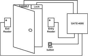 Controller uses one relay output, one door contact, two or one reader and exit button. Thus, controller can be used for entry-exit control (with one entry reader and one exit reader, button is optional) or for entry control (with entry reader and exit button). In this mode controller generates all events from door contact (door contact): Passage is committed , Passage has not been committed , Door is not closed , Door is closed, Door is forced open . Controller supports one memory bank for cardholder records (up to 8144 cardholders). 3.2. Two-doors operating mode. In this operating mode controller supports entry access control functions for two independent doors. 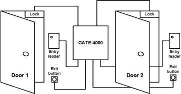 Controller uses two relay outputs, two readers and two exit buttons. Door contacts are not used. Thus, controller can be used for two doors with reader for entry and button for exit. The Passage is committed event is generated simultaneously with the Access is granted event on the fact of key identification and switching the relay on. Controller supports two independent memory banks for cardholder records (up to 4072 cardholders per each door). 3.3 Turnstile operating mode. In this operating mode controller supports entry-exit access control functions for one turnstile. 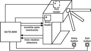 Controller uses two relay outputs, two door contacts (for rotation detectors), two or one reader and two or one exit button. Thus, controller can be used for entry-exit control (with reader1 and button1 for entry and reader2 and button2 for exit) or for entry control (with one reader and one button). In this mode controller generates all events from door contact. Controller supports one memory bank for cardholder records (up to 8144 cardholders). 3.4 Gateway operating mode. In this operating mode controller supports one two-door access point (gateway). 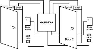 Controller uses two relay outputs, two door contacts, two readers and two exit buttons. This operating mode is used to organize one-way gateway. If one of two doors (or both) is open readers and buttons are blocked. Thus, the first door can be unlocked only when the second door is physically closed. In this mode controller generates all events from door contact. Controller supports one memory bank for cardholder records (up to 8144 cardholders). 4. Controller organization Controller is connected to external devices and to a network by means of demountable screw connectors grouped by functional purpose. Controller adjustment is performed by means of switches (jumpers). Jumpers and connectors arrangement on the controller board is shown in figure below.
Readers wiring 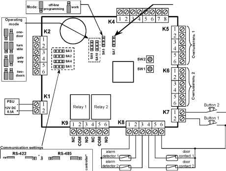
* controller is the last one in a communication line (this setting connect the terminating resistor on the controller board) 5. Controller installation and connection The basic requirements to controller installation а. The controllers should be mounted in a secure location providing normal temperature and humidity levels. б. Controllers and communication cables must be located at a minimum distance of one meter from any high voltage equipment or wiring, at a minimum distance of 2 meters from electrical equipment susceptible of generating electrical interference, at a minimum distance of 1 meter from telephone equipment or lines and, at a minimum of 8 meters from any transmitting equipment. в. In case of entering the controller from cold conditions it is necessary to wait not less than two hours at a room temperature before connection the controller to the power supply unit. Connecting the power supply Controller and connected readers as a rule use the same power supply unit (PSU). To provide failure-free operation of the controller in case of power failure use uninterruptible power supply unit. The maximal distance between the controller and the PSU depends on type of the cable, used for connection.
K1 connector is used for PSU connection (+12V DC, 0,5A) PSU 12V 0.5A When power is present, the red power LED (located on the controller board near the K1 connector) will be on. Connecting the locking devices Use the K9 connector to connect to the controller one or two locking devices (lock, strike etc). To guarantee stable functioning of the controller use the different PSU and different cables for powering the controller and the locking device. The K9 connector uses COM , NO , NC contacts for two relays (R1 and R2) COM - the central contact of the relay NO - the normally open contact of the relay. NC - the normally closed contact of the relay.
COM NO NC COM In case of connection to the controller DC locking devices (electromagnetic or electromechanical locks) they need to be shunted by diodes for prevention sealing the relay contacts (these diodes are included in the box) Connection schemes of locking devices will differ depending on type of mechanisms and an operating mode of the controller. The basic variants of connection are shown in the pictures below. Example 1. Connecting the electromagnetic lock. One-door operating mode
12...30V Lock Example 2. Connecting the electromechanical lock. One-door operating mode nc com no nc com no 12...30V Lock Example 3. Connecting the electromagnetic lock. Two-door & gateway operating mode nc com no nc com no PSU 12...30V Lock 1 Lock 2 Example 4. Connecting the electromechanical lock. Two-door & gateway operating mode nc com no nc com no PSU 12...30V Lock 1 -H>Hr Lock 2 Example 5. Connecting the turnstile. Turnstile operating mode nc com no nc com no
Open turnstile Connecting the alarm inputs Use the K8 connector to connect to the controller one or two door contacts and two auxiliary alarm detectors. The door contacts and the alarm detectors should have normally closed (NC) output. The controller is continuously monitoring the state of the inputs. In case of opening the input circuit the according event is generated (Door is forced open and Input is alarmed). All unused inputs must be connected to the ground contact. The basic variants of connecting the door contacts and the alarm detectors are shown in the pictures below. Example 1. One-door operating mode K8 Ground -I Alarm input 2 Alarm input 1 Ground door contact Example 2. Turnstile operating mode K8 Ground l Alarm input 2- Alarm input 1 Ground rotation detectors Example 3. Two-door operating mode K8 Ground l Alarm input 2-Alarm input 1 - Example 4. Gateway operating mode Ground l Alarm input 2-Alarm input 1 - Ground Door cont.2 Connecting the exit buttons Use the K7 connector to connect to the controller one or two exit buttons. Button 1 switch on relay R1, Button 2 switch on relay R2 (except the one-door operating mode) Ь butt
buttons 2 1 Ground If cables from the controller to the buttons are more than 3 meters long then, to avoid false inputs closing signals, the button inputs should be shunted to +12V contact by 1kOhms resistors. Connecting the readers Use the K5 and K6 connectors to connect to the controller one or two readers. The connected readers must have the same output interface. So, it is possible to use two readers with Wiegand interface or two readers with 1-Wire interface. Reader 1 is connected to the K5 connector. It always controls switching the relay R1. Reader 2 is connected to the K6 connector. It controls switching the relay R1 (in one-door operating mode) and relay R2 in two-doors, turnstile and gateway. Connect the readers to the controller according to the table below.
Note: * Touch-memory emulator is used by contactless proximity readers supporting 1-Wire output interface. ** LED is an open collector output. Cable requirements for connecting the Touch-memory readers to the controller:
It is recommended to connect Proximity readers to the controller by shielded multicore signal cable with diameter of one core not less than 0,22mm. To increase a noise-immunity of a signal the shield of the cable must be connected to the Ground contact only from the controller side. Using a proper cable, Proximity readers may be located up to a distance of 100 m from the controller (exact data about cable requirements and maximal distance you should find in the instruction for the reader). Examples of connecting the readers Example 1: connecting the reader of Matrix series (Matrix II(m)-EH and Matrix IV EH Keys) I K5(K6) i-Г7>
Example 2: connecting the reader PW-101 with controlled LED/ Beep outputs K5(K6)
Example 3: connecting the Touch-Memory reader Example 4: connecting the magnetic stripe reader with LED indication KDR-1321/ KDR-1351 (TTL-level) I K5(K6) Touch-memory reader with LED DS1990 (1-Wirel Ground + LED -LEDcAB K5(K6)
+ 5 VDC Ground 6. The working mode The working mode is the main controller mode. For switching the controller to the working mode set SA5 jumper to work position. When a key or a card is presented to a reader for not less then 0.5 seconds, the reader sends its code number to the controller. The controller compares the number to an access control list (ACL), stored in controller memory. ACL consists of numbers of keys/cards and their access level based on seven week schedules. If there is match between the key/card and ACL, the controller switch on the green LED on board and operates a relay that in turn unlocks the locking device. When access is denied based on the ACL, the controller switch on the red LED on board the locking device stays locked. Configuration and programming of the controller is performed from the computer by means of special Gate software. If the controller is not connected to the computer, it can be configured by the use of off-line programming mode. 1 2 |
||||||||||||||||||||||||||||||||||||||||||||||||||||||||||||||||||||||||||||||||||||||||||||||||||||||||||||||||||||||||||||||||||||||||||||||||||||||||||||||||||||||||||||||||||||||||||||||||||||||||||||||||||||||||||||||||||||||||||||||||||||||||||||||||||||||||||||||||||||||||||||||||||||||||||||||||||||||||||||||||||||||||||||||||||||||||||||||||||||||||||||||||||||||||||||||||||