
8(903)201-21-74
ООО "ЧетыреДатчика"
|
Оператор: 8(903)201-21-74 ООО "ЧетыреДатчика" |
|
Оператор: 8(903)201-21-74 ООО "ЧетыреДатчика" |
Главная страница Gate-4000 1 2 7. Time settings of the controller The controller has three time setting: The relay time The passing time The door opening time The relay time can be configured either from the computer (by means the special Gate software) or using off-line programming of the controller (step 4). Two other time settings can be configured only from the computer. 1) Using the controller without door contacts. This configuration is set in the controller by default. It is also used automatically when the controller is switched to the two-door operating mode. In this variant the passing time value is set to 0. The value of the relay time defines the time of switching on the relay regardless on the door contact presence and state. The reader indication time is 0,5 seconds. The Passage is committed event is generated automatically simultaneously with the Access is granted event. 2) Using the controller with door contacts. This variant activates when no zero passing time is set. In this case the passing time could not be less than the relay time. The time settings of the controller have the next meaning: The relay time defines the time of switching on the relay and the reader indication time. The passing time defines the time interval, when the door contact can be open without the alarm event. The readers and buttons are being locked for this time If this time has expired and the door contact has not been open, then the Passage has not been committed event is generated. If the door contact is open before this time has expired, then the Passage is committed is generated, the relay is switching off, the control of the passing time stops and the control of the door opening time starts. The door opening time is controlled from the moment of the valid door opening. If this time has expired and the door contact has not been closed, then the Door is not closed event is generated. If the value of this time is 0 (the default setting), then the control of the door opening is not performed. Attention! If the second variant is used and the door contacts were not connected to the controller, then the relay will switch for 0,5 second independently of the relay time settings. 8. Off-line programming of the controller Off-line programming of the controller includes five steps: 1. Adding key number* into the memory bank 1 (for the reader 1) or in the memory bank 2 (for the reader 2) 2. Deleting key number* from the memory bank 1 or 2 3. Formatting the key number memory bank* 1 or 2 (removing all key numbers from the memory bank). 4. Relay time programming** for the relays R1 and R2. 5. Restoring the default (factory) settings. The controller successively goes from one step to another. Notes: * These settings depend on the operating mode of the controller. In one-door , turnstile and gateway modes one common memory bank is used (up to 8144 key records). In two-door mode two independent memory banks are used (up to 4072 key records per each bank). ** This setting depends on the operating mode of the controller. In one-door mode one relay is used. In turnstile , two-door and gateway modes two relays are used. To enter off-line programming, turn off the power of the controller, switch the SA5 jumper into the off-line programming position and briefly press the SW2 button. In one second the controller will change to the first programming step. To exit off-line programming, switch the SA5 jumper into the work position and press the SW1 button. The controller will change into the working mode. The current state of programming is indicated by green and red LEDs. Step 1. Adding key number Step indication: the red LED is On, the green LED is Off. To add a new key number into the memory bank present the key to the appropriate reader (1 or 2) for the time not less than 0,5 sec. If the number of this key is already written in the controller memory, the LED state will not change. Otherwise the key number will be written into the controller memory and red and green LEDs will blink three times. In one-door , turnstile , and gateway operating modes one common memory bank is used. Adding new keys is performed by means of the reader 1. In two-door mode two independent memory banks are used. Adding new keys is performed by means of the readers 1 and 2. To go from step 1 to step 2 press the SW1 button. Step 2. Deleting key number Step indication: the red LED is Off, the green LED is On. To delete a key number from the memory bank present the key to the appropriate reader (1 or 2) for the time not less than 0,5 sec. If there is not this key number in the controller memory, the LED state will not change. Otherwise the key number will be removed from the controller memory and red and green LEDs will blink three times.. In one-door , turnstile , and gateway operating modes one common memory bank is used. Deleting keys is performed by means of the reader 1. In two-door mode two independent memory banks are used. Deleting keys is performed by means of the readers 1 and 2 To go from step 2 to step 3 press the SW1 button. Step 3. Formatting the key number memory bank This step allows is used to delete all the key numbers from the controller memory. In one-door , turnstile , and gateway operating modes one common memory bank is being formatted. In two-door mode two memory banks are being formatted independently. Memory bank 1 is being formatted the first. Step indication: the red LED is blinking, the green LED is Off. Press the SW2 button to start the operation. Both LEDs will be Off for 75 seconds and then will blink three times. This means that the memory bank 1 has been formatted successfully. After this both LEDs will be blinking alternately for 2-3 seconds and then they will return to the initial step indication. It means readiness of the controller to formatting the memory bank 2. Formatting the memory bank 2 is performed similarly. When formatting is finished the controller will automatically go to the next programming step (step 4). If formatting the memory bank 1 is not required then press the SW1 button to skip the operation and go to formatting the memory bank 2. If formatting the memory bank 2 is not required then press the SW1 button to go to the next programming step (step 4). Step 4. Relay time programming Step indication: the red LED is blinking, the green LED is On. To add a new key number into the memory bank present the key to the appropriate reader (1 or 2) for the time not less Relay R1 time is programmed the first. This time can vary from 0,5 seconds (for electromechanical locks) to 25 seconds (for magnetic or complex motorized locks). The default setting is 0,5 seconds. To change the time setting, press and hold the SW1 button. The duration of red LED blinking will grow in accordance with the new time value. Press the SW2 button to save the new setting. After this the both LEDs will be blinking alternately for 1-2 seconds, the new relay time value will be saved into the controller memory and then the controller will go to the second part of the step 4 - programming the Relay R2. Indication and programming the relay R2 time are completely similar. In one-door operating mode only one relay (R1) is programmed. In turnstile , two-door and gateway modes two relays (R1 and R2) are programmed. Step 5. Restoring the default (factory) settings In this step the base controller settings are returned to their default values: 1. The network address of the controller is set to 001 . The network address is used to call the controller by RS485/RS422 bus. Each controller in one branch (one RS485/422 bus) must have its own unique address from 1 to 254. 2. The borders of key memory banks are returned to their maximal values 8144 (4072) records (see Note 7). 3. The passing time and the door is not closed alarm time are set to 0 seconds. Step indication: the red LED and the green LED are blinking quickly. To start the operation, press the SW2 button. Then both LEDs will blink three times. All steps of programming are finished now. Press the SW1 button to go back to the first step. To exit off-line programming of the controller switch the SA5 jumper into the work position and press the SW1 button 9. Connecting the controllers to the RS-485/ RS-422 bus The GATE-4000 controllers are linked together using the RS-485 or RS-422 communication bus. They are connected to the computer through the special interface converter. The special Gate software is used to configure the controller, to program the cards/keys and access levels, to read events from the controllers and to create different reports. In any case (with or without the computer) the decision about access permission or refusal is made by the controller and. This decision is based on the access control list, stored in the controller memory. Connecting the controller to the RS-485 bus -TGI- USB or RS-232 Connecting the controller to the RS-422 bus 
Convener Controller 1 Controller Controller N (the last) Two variants of connecting the controllers to the computer are shown in the picture above. The last term means, that the controller is the final one in line. The controllers are linked successively one after another. Each controller has its unique number/ address (in a range from 1 to 254) to be addressed from the computer. The communication speed is always 19200 baud. Use the 5 cat twisted pair cable to connect the controller to the communication bus. The distance between the converter and the last controller cannot exceed 1200 meters Before connecting the controller to a communication network it is necessary to check its network setting (network address and interface address, configured by SA1 - SA4 jumpers). All new controllers have initial address 001. Address 255 is reserved for emergency situation. It is indicated by permanently lighting of green LED on the controller board. This address may be set in case of some serious collisions during the controller operation. Use the К2 connector for connecting the controller to the communication bus. Use SA1 - SA4 jumpers for setting the appropriate communication mode. Converter 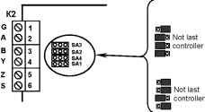 Communication settings RS-422 interface Last controller RS-485 interface Last controller А & В lines - two wires in one pair Y & Z lines - two wires in one pair G line (Ground) or S line (Ground through the 100 Ohms resistor) 5 cat twisted pair cable If the shielded cable is used then connect the shield wire to G contacts of the controllers and the converter. If the normal wiring (to G contact) does not allow to establish stable connection, then use S contact instead of G contact. 10. Network configuration example Here is an example of configuring the controller network consisting of ten controllers. Step 1 Step 2. Step 3. Step 4. Step 5. Step 6. Step 7. Mount the controllers, connect the controllers to the RS485 (RS422) bus successively each after another Check the correctness of the network connections Disconnect the network connectors (K2) from all controllers except the last one (which is configured as the last controller ) Using the Gate-Find software scan the network and find the controller with address 001 . Change the address of the controller 001 to 010 Mount the network connector (K2) on the next controller and scan the network again Find two controllers in the network with addresses 001 and 010 . Change the address of the controller 001 to 009 . Mount the network connector (K2) on the next controller and scan the network again. Find the controllers with addresses 001 , 009 and 010 . Change the address of the controller 001 to 008 . Continue the process similarly until we get the network of the controllers with addresses from 001 to 010
Appendix 1: Wiring the controller in one-door operating mode 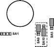 ni-oo1SA2 pnr.nSA3 IOOOISA4 Relay 1 Relay 2 0000 To the door locking device Exit button door contact Appendix 2: Wiring the controller in turnstile operating mode 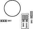 IOOOISA2 IOOOISA3 ШЖШ SA4 О О Relay 1 Relay 2 Open turnstile for Entry Open turnstile for Exit Open to exit button Open to entry button from entry rotation detector from exit rotation detector Appendix 3: Wiring the controller in two-door operating mode  looelSA2 i6t aiSA3 [oTo]SA4
SW2 SW1 о Ш to Door 1 locking device to Door 2 locking device Door 2 exit button Door 1 exit button Appendix 4: Wiring the controller in gateway operating mode 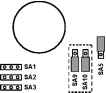 ШШiSA4 SW2 SW1 Ш о Relay 1 Relay 2 0000 to Door 1 locking device to Door 2 locking device Door 2 exit button Door 1 exit button Door 1 contact Door 2 contact -P==C- Notes Notes 1 2 |
|||||||||||||||||||||||||||||||||||||||||||||||||||||||||||||||||||||||||||||||||||||||||||||||||||||||||||||||||||||||||||||||||||||||||||||||||||||||||||||||||||||||||||||||||||||||||||||||||||||||||||||||||||||||||||||||||||||||||||||||||||||||||||||||||||||||||||||||||||||||||||||||||||||||||||||||||||||||||||||||||||||||||||||||||||||||||||||||||||||||||||||||||||||||||||||||||||||||||||